Copyright 2015 by Maxford USA
Page
15
RUMPLER TAUBE / Doc. Nbr. S160113
6.
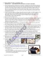
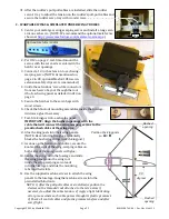
Use springs to attach the pre-installed
simulated under-side wing wires to the
landing gear’s cotter pins as pictured at
the right.
7.
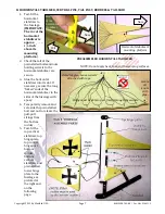
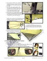
Draw the remaining simulated under-
side wing wires toward the lower end of
the pilot’s control stick and allow the
string to slide through the swivels to
equalize the tension on the strings.
8.
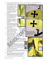
Using a bolt, nut, 2 swivels and 2 springs,
attach the preinstalled simulated under-
side wing wires to the lower end of the pilot’s
control stick as pictured at the right.
(NOTE: Any twisted pair of simulated horizontal
stabilizer or wing tip-warping cables may be
separated as shown below.)
9.
Install the wing tip wires as shown.
(NOTE: These wires are optional,
only for appearance.)
H.
COCKPIT HATCHES, OPTIONAL PILOT FIGURE(S)
and OPTIONAL DUMMY ENGINE
1.
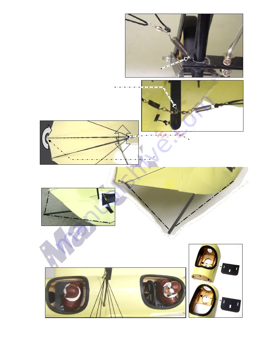
If you will install optional pilot figures:
a.
Test-fit the pilot mounting platforms (shown at the right) onto the
cockpit hatches and secure the platforms with glue.
b.
Position and glue
1/8
-scale pilot figures onto their platforms.
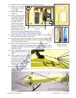
If necessary, gently separate any pair of
twisted strings and allow their shared swivel
to “unwind” the strings as pictured at the left.
Open end of
cotter pin


