Copyright 2015 by Maxford USA
Page
3
RUMPLER TAUBE / Doc. Nbr. S160113
14.
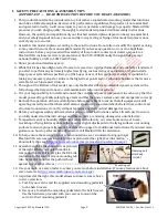
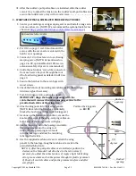
String may be supplied to pull your servo’s lead and servo
extension through the wing to your receiver; however, you
may find it easier to use masking tape to temporarily
attach the connector to the end of a length of coat-hanger
wire, then use the wire to pull the lead and connector
through the wing as pictured at the right. Guide the servo
into the servo bay, cover the servo bay with the servo-hatch and secure the hatch with screws or glue.
15.
After you determine each wood-screw’s location, drill a guide hole, drive the screw into the hole, then
remove the screw and apply thin CA adhesive to harden and strengthen the wood.
16.
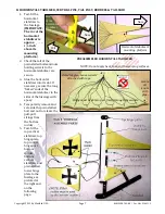
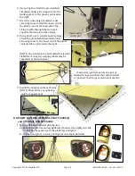
To use a crimp tube for attaching a cable (such as to a threaded rod as pictured below):
a.
Slide the crimp-tube onto the end of the cable.
b.
Guide the end of the cable through the opening in
the threaded rod.
c.
Bring the end of the cable back into and all the way
through the crimp tube.
d.
Loop the end of the cable back into the crimp tube, adjust the looped
end of the cable, then use pliers to firmly squeeze along the length of
the crimp tube to securely crimp the tube onto the cable.
(NOTE: For your safety, do not leave any strands of wire poking out
from the end of any crimp tube. Exposed small steel strands can be
sharp enough to cut or abrade skin!)
17.
After a clevis is adjusted on its threaded rod, anchor the threaded rod inside the clevis by snugging a
lock nut (if supplied) against the clevis and/or permanently secure the clevis to the rod with epoxy.
18.
Any clevises included with this model may be made of plastic or metal. A conserva-
tive modeler may hold the clevis closed by adding a spring or a small piece of
plastic or heat-shrink tubing as pictured at the right.
19.
If Mylar covering material hides a CA hinge’s slot, find and open the slot by care-
fully pressing with a fingernail or sharp hobby knife.
20.
To obtain good wood-to-wood gluing surfaces, use the tip of a hot soldering iron to burn through and
remove any Mylar covering material. (Be careful to not cut into the wood.)
21.
We recommend 30-minute epoxy for permanent attachment of critical parts.
22.
Periodically check any preinstalled magnets to ensure they remain securely postitioned.
23.
If you are not an experienced ARF assembler or R/C pilot, we strongly urge you to get assistance from an
experienced R/C assembler and pilot.
24.
Apply threadlock compound or CA adhesive to secure all hardware from vibration.
25.
Use epoxy to permanently attach and reinforce critical airframe assemblies. If you have concern about
the security of any factory fabrication procedure(s), you may apply extra epoxy adhesive around the
perimeter of such part(s) as a safety precaution.
26.
Production details (such as included hardware items and/or Mylar or paint colors) may vary.
27.
This model may include some plastic, fiberglass and/or carbon-fiber-reinforced
parts. If you drill, grind or sand any such part, always wear safety goggles, a particle mask and rubber
gloves to guard yourself from eye, skin and respiratory-tract irritation. Never blow into such a part as
the dust may blow back into your face.
28.
Periodically check the Mylar covering material’s joints and surfaces; if necessary, carefully use an iron
(do NOT set the iron’s temperature too high) to secure the edges and to tighten any loosened areas. If a
flying surface appears warped or twisted:
a.
Carefully use a covering iron to make sure that all of the edges of the covering (and the edges of any
trim made from covering material) are sealed where they wrap around the leading and trailing edges
and the wingtips.
b.
Determine which way the control surface must be twisted to correct the warp/twist.


