background image

DS3234

Extremely Accurate SPI Bus RTC

with Integrated Crystal and SRAM 

Maxim Integrated  |  12

www.maximintegrated.com

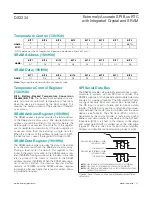
Figure 1. Address Map for DS3234 Timekeeping Registers and SRAM 

Note: 

Unless otherwise specified, the registers’ state is not defined when power is first applied. Bits defined as 0 cannot be written

to 1 and will always read 0.

ADDRE

SS

READ/WRITE

M

S

B

BIT 7

BIT 6

BIT 5

BIT 4

BIT 3

BIT 2

BIT 1

L

S

B

BIT 0

FUNCTION

RANGE

00h

80h

0

10 Seconds

Seconds

Seconds

00–59

01h

81h

0

10 Minutes

Minutes

Minutes

00–59

AM

/PM

02h

82h

0

12/

24

20 hr

10 hr

Hour

Hours

1-12 +

AM

 /PM

00-23

03h

83h

0

0

0

0

0

Day

Day

1-7

04h

84h

0

0

10 Date

Date

Date

01-31

05h

85h

Century

0

0

10 Mo

Month

Month/

Century

01-12 +
Century

06h

86h

10 Year

Year

Year

00-99

07h

87h

A1M1

10 Seconds

Seconds

Alarm 1

Seconds

00-59

08h

88h

A1M2

10 Minutes

Minutes

Alarm 1
Minutes

00-59

AM

/PM

09h

89h

A1M3

12/

24

20 hr

10 hr

Hour

Alarm 1 Hours

1-12 +

AM

 /PM

00-23

0Ah

8Ah

A1M4

DY/

DT

0

10 Date

Day

Date

Alarm 1 Day

Alarm 1 Date

1-7

01-31

0Bh

8Bh

A2M2

10 Minutes

Minutes

Alarm 2
Minutes

00-59

AM

/PM

0Ch

8Ch

A2M3

12/

24

20 hr

10 hr

Hour

Alarm 2 Hours

1-12 +

AM

 /PM

00-23

0Dh

8Dh

A2M4

DY/

DT

0

10 Date

Day

Date

Alarm 2 Day

Alarm 2 Date

1-7

01-31

0Eh

8Eh

EOSC

BBSQW

CONV

RS2

RS1

INTCN

A2IE

A1IE

Control

0Fh

8Fh

OSF

BB32kHz

CRATE1

CRATE0

EN32kHz

BSY

A2F

A1F

Control/

Status

10h

90h

SIGN

DATA

DATA

DATA

DATA

DATA

DATA

DATA

Crystal Aging

Offset

11h

91h

SIGN

DATA

DATA

DATA

DATA

DATA

DATA

DATA

Temp MSB

Read Only

12h

92h

DATA

DATA

0

0

0

0

0

0

Temp LSB

Read Only

13h

93h

0

0

0

0

0

0

0

BB_TD

Disable Temp

Conversions

14h–17h

94h–97h

Reserved

18h

98h

A7

A6

A5

A4

A3

A2

A1

A0

SRAM

Address

19h

99h

D7

D6

D5

D4

D3

D2

D1

D0

SRAM Data

Summary of Contents for DS3234

Page 1: ...M indicator Two programmable time of day alarms and a programmable square wave output are provided Address and data are transferred serially by an SPI bidirectional bus Applications Servers Utility Power Meters Telematics GPS Benefits and Features Highly Accurate RTC with Integrated Crystal and SRAM Completely Manages All Timekeeping Functions Accuracy 2ppm from 0 C to 40 C Accuracy 3 5ppm from 40...

Page 2: ...Voltage VBAT 2 0 3 0 3 8 V Logic 1 Input CS SCLK DIN VIH 0 7 x VCC VCC 0 3 V 2 0V VCC 3 63V 0 3 0 2 x VCC Logic 0 Input CS SCLK DIN RST VIL 3 63V VCC 5 5V 0 3 0 7 V Electrical Characteristics VCC 2 0V to 5 5V VCC active supply see Table 1 TA 40 C to 85 C unless otherwise noted Typical values are at VCC 3 3V VBAT 3 0V and TA 25 C unless otherwise noted TCXO operation guaranteed from 2 3V to 5 5V on...

Page 3: ...akage IOL RST high impedance Note 6 200 10 µA TCXO VCC 2 3V to 5 5V VBAT 2 3V to 3 8V TA 40 C to 85 C unless otherwise noted Notes 2 and 3 Output Frequency fOUT VCC 3 3V or VBAT 3 3V 32 768 kHz 0 C to 40 C 2 2 Frequency Stability vs Temperature Δf fOUT VCC 3 3V or VBAT 3 3V 40 C to 0 C and 40 C to 85 C 3 5 3 5 ppm Frequency Stability vs Voltage Δf V 1 ppm V 40 C 0 7 25 C 0 1 70 C 0 4 Trim Register...

Page 4: ...V 220 ns SCLK Rise and Fall tR tF 200 ns CS to SCLK Setup tCC 400 ns 2 7V VCC 5 5V 100 SCLK to CS Hold tCCH 2 0V VCC 2 7V 200 ns CS Inactive Time tCWH 400 ns CS to Output High Impedance tCDZ Note 8 40 ns Pushbutton Debounce PBDB 250 ms Reset Active Time tRST 250 ms Oscillator Stop Flag OSF Delay tOSF Note 9 100 ms Temperature Conversion Time tCONV 125 200 ms Power Switch Characteristics 5 TA 40 C ...

Page 5: ...rsion current CRATE1 CRATE0 0 Note 6 The RST pin has an internal 50kΩ nominal pullup resistor to VCC Note 7 Measured at VOH 0 8 x VCC or VOL 0 2 x VCC Measured from the 50 point of SCLK to the VOH minimum of DOUT Note 8 With 50pF load Note 9 The parameter tOSF is the period of time the oscillator must be stopped for the OSF flag to be set over the voltage range of 0V VCC VCC MAX and 2 3V VBAT VBAT...

Page 6: ...d Transfer HIGH IMPEDANCE CS SCLK DIN W R tDC tCL tCH tCDD tCDZ tCDH tCC tCCS tR tF A6 A0 D0 WRITE ADDRESS BYTE NOTE SCLK CAN BE EITHER POLARITY SHOWN FOR CPOL 1 READ DATA BYTE DOUT D7 Timing Diagram SPI Write Transfer CS SCLK DIN W R tDC tCDH tCL tCH tCCH tCWH tF tR tCC A6 A0 WRITE ADDRESS BYTE WRITE DATA BYTE D7 D0 DOUT HIGH IMPEDANCE ...

Page 7: ...650 750 800 850 600 40 VBAT 3 4V VBAT 3 0V VCC 0V BB32kHz 0 BBSQW 0 FREQUENCY DEVIATION vs TEMPERATURE vs AGING VALUE DS3234 toc04 TEMPERATURE C FREQUENCY DEVIATION ppm 80 60 40 20 0 20 25 15 5 5 15 25 35 65 55 45 35 45 40 AGING 128 AGING 33 AGING 127 AGING 0 AGING 32 ICCA vs DOUT LOAD DS3234 toc05 CAPACITANCE pF SUPPLY CURRENT μA 40 30 20 10 250 350 300 400 450 500 200 0 SCLK 4MHz DELTA TIME AND ...

Page 8: ...his pin is an open drain input output It indicates the status of VCC relative to the VPF specification As VCC falls below VPF the RST pin is driven low When VCC exceeds VPF for tRST the RST pin is driven high impedance The active low open drain output is combined with a debounced pushbutton input function This pin can be activated by a pushbutton reset request It has an internal 50k_ nominal value...

Page 9: ...sed by temperature variations The DS3234 provides user selectable sample rates This allows the user to select a temperature sensor sample rate that allows for vari ous temperature rates of change while minimizing cur rent consumption by temperature sensor sampling The user should select a sample rate based upon the expected temperature rate of change with faster sam ple rates for applications wher...

Page 10: ... when VCC drops below VBAT After VCC returns above both VPF and VBAT read and write access is allowed after RST goes high Table 1 To preserve the battery the first time VBAT is applied to the device the oscillator does not start up until VCC crosses VPF After the first time VCC is ramped up the oscillator starts up and the VBAT source powers the oscillator during power down and keeps the oscillato...

Page 11: ...in case the main registers update during a read SPI Interface The DS3234 operates as a slave device on the SPI seri al bus Access is obtained by selecting the part by the CS pin and clocking data into out of the part using the SCLK and DIN DOUT pins Multiple byte transfers are supported within one CS low period The SPI on the DS3234 interface is accessible whenever VCC is above either VBAT or VPF ...

Page 12: ...99 07h 87h A1M1 10 Seconds Seconds Alarm 1 Seconds 00 59 08h 88h A1M2 10 Minutes Minutes Alarm 1 Minutes 00 59 AM PM 09h 89h A1M3 12 24 20 hr 10 hr Hour Alarm 1 Hours 1 12 AM PM 00 23 0Ah 8Ah A1M4 DY DT 0 10 Date Day Date Alarm 1 Day Alarm 1 Date 1 7 01 31 0Bh 8Bh A2M2 10 Minutes Minutes Alarm 2 Minutes 00 59 AM PM 0Ch 8Ch A2M3 12 24 20 hr 10 hr Hour Alarm 2 Hours 1 12 AM PM 00 23 0Dh 8Dh A2M4 DY ...

Page 13: ... the date of the month If DY DT is written to logic 0 the alarm will be the result of a match with date of the month If DY DT is written to logic 1 the alarm will be the result of a match with day of the week When the RTC register values match alarm register set tings the corresponding Alarm Flag A1F or A2F bit is set to logic 1 If the corresponding Alarm Interrupt Enable A1IE or A2IE is also set ...

Page 14: ...me both CONV and BSY go to 0 The CONV bit should be used when monitoring the status of a user initiated conversion Bits 4 and 3 Rate Select RS2 and RS1 These bits control the frequency of the square wave output when the square wave has been enabled The following table shows the square wave frequencies that can be select ed with the RS bits These bits are both set to logic 1 8 192kHz when power is ...

Page 15: ... accuracy These bits are set to logic 0 when power is first applied Bit 3 Enable 32kHz Output EN32kHz This bit indi cates the status of the 32kHz pin When set to logic 1 the 32kHz pin is enabled and outputs a 32 768kHz square wave signal When set to logic 0 the 32kHz pin is low The initial power up state of this bit is logic 1 and a 32 768kHz square wave signal appears at the 32kHz pin after a pow...

Page 16: ...logic 0 when power is first applied Use of the aging register is not needed to achieve the accuracy as defined in the EC tables but could be used to help compensate for aging at a given tempera ture See the Typical Operating Characteristics section for a graph showing the effect of the register on accu racy over temperature Temperature Registers 11h 12h Temperature is represented as a 10 bit code ...

Page 17: ...SPI serial data bus to com municate in systems with an SPI host controller The DS3234 supports both single byte and multiple byte data transfers for maximum flexibility The DIN and DOUT pins are the serial data input and output pins respectively The CS input is used to initiate and terminate a data transfer The SCLK pin is used to synchronize data move ment between the master microcontroller and t...

Page 18: ...lace If the MSB is 0 one or more read cycles occur If the MSB is 1 one or more write cycles occur MODE CS SCLK DIN DOUT Disable H Input Disabled Input Disabled High Impedance CPOL 1 SCLK Rising Write L CPOL 0 SCLK Falling Data Bit Latch High Impedance CPOL 1 SCLK Falling Read L CPOL 0 SCLK Rising X Next Data Bit Shift Read Invalid Location L Don t Care Don t Care High Impedance Table 3 SPI Pin Fun...

Page 19: ...e the internal and user copies of the time are only synchronized on these two events an alarm condi tion can occur internally and activate the INT SQW pin independently of the user data If the SRAM is accessed by reading address 19h or writing address 99h the SRAM data register the con tents of the SRAM address register are automatically incremented after the first access and all data cycles will ...

Page 20: ...PE PACKAGE CODE OUTLINE NO LAND PATTERN NO 20 SO W20 H2 21 0042 90 0108 Package Information For the latest package outline information and land patterns foot prints go to www maximintegrated com packages Note that a or in the package code indicates RoHS status only Package drawings may show a different suffix character but the drawing pertains to the package regardless of RoHS status ...

Page 21: ...he Recommended DC Operating Conditions table and added verbiage about the pullup to the Pin Description table for INT SQW 2 8 In the Electrical Characteristics table added CRATE1 CRATE0 0 to the IBATT parameter and changed the symbols for Timekeeping Battery Current Temperature Conversion Current and Data Retention Current from IBAT ITC and IBATTC to IBATT IBATTC and IBATTDR respectively 3 In the ...

Page 22: ...Mouser Electronics Authorized Distributor Click to View Pricing Inventory Delivery Lifecycle Information Maxim Integrated DS3234S DS3234S T R DS3234SN DS3234SN T R ...

Reviews: