MAX32600 User’s Guide
Analog Front End
8.3 ADC
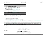
V
I
PGA Mode (
Min V
I
Max V
I
Notes
Unipolar
Not Applicable
Single-Ended
Ai
2X
0
V
REF
/2
Unipolar
Not Applicable
Single-Ended
Ai
4X
0
V
REF
/4
Unipolar
Not Applicable
Single-Ended
Ai
8X
0
V
REF
/8
Unipolar
Not Applicable
Differential
AiP-AiN
1X (Bypass)
0
V
REF
AiP
>
AiN
Unipolar
Not Applicable
Differential
AiP-AiN
2X
0
V
REF
/2
AiP
>
AiN
Unipolar
Not Applicable
Differential
AiP-AiN
4X
0
V
REF
/4
AiP
>
AiN
Unipolar
Not Applicable
Differential
AiP-AiN
8X
0
V
REF
/8
AiP
>
AiN
Bipolar
V
REF
Differential
AiP-AiN
1X (Bypass)
-V
REF
V
REF
Bipolar
V
REF
Differential
AiP-AiN
2X
-V
REF
/2
V
REF
/2
Bipolar
V
REF
Differential
AiP-AiN
4X
-V
REF
/4
V
REF
/4
Bipolar
V
REF
Differential
AiP-AiN
8X
-V
REF
/8
V
REF
/8
Bipolar
V
REF
/2
Differential
AiP-AiN
1X (Bypass)
-V
REF
/2
V
REF
/2
Bipolar
V
REF
/2
Differential
AiP-AiN
2X
-V
REF
/4
V
REF
/4
Bipolar
V
REF
/2
Differential
AiP-AiN
4X
-V
REF
/8
V
REF
/8
Bipolar
V
REF
/2
Differential
AiP-AiN
8X
-V
REF
/16
V
REF
/16
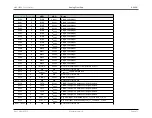
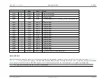
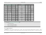
Note
Explanation of
Input Voltage to the Receive Path Table
values:
• V
I
: Effective Input Voltage
• Minimum V
I
with Digital Output 0x0001
• Maximum V
I
with Digital Output 0xFFFF
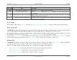
8.3.4.8
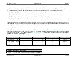
Sample Rate Calculation
The
MAX32600
ADC supports two primary measurement modes for the ADC: Low Power Measurement Mode and High Speed Measurement Mode. Low Power
Measurement Mode uses significantly less power than High Speed Measurement Mode by putting the ADC and PGA, if enabled, in a sleep state between samples.
Rev.1.3 April 2015
Maxim Integrated
Page 417

