MAX32600 User’s Guide
Analog Front End
8.4 DAC
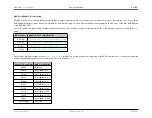
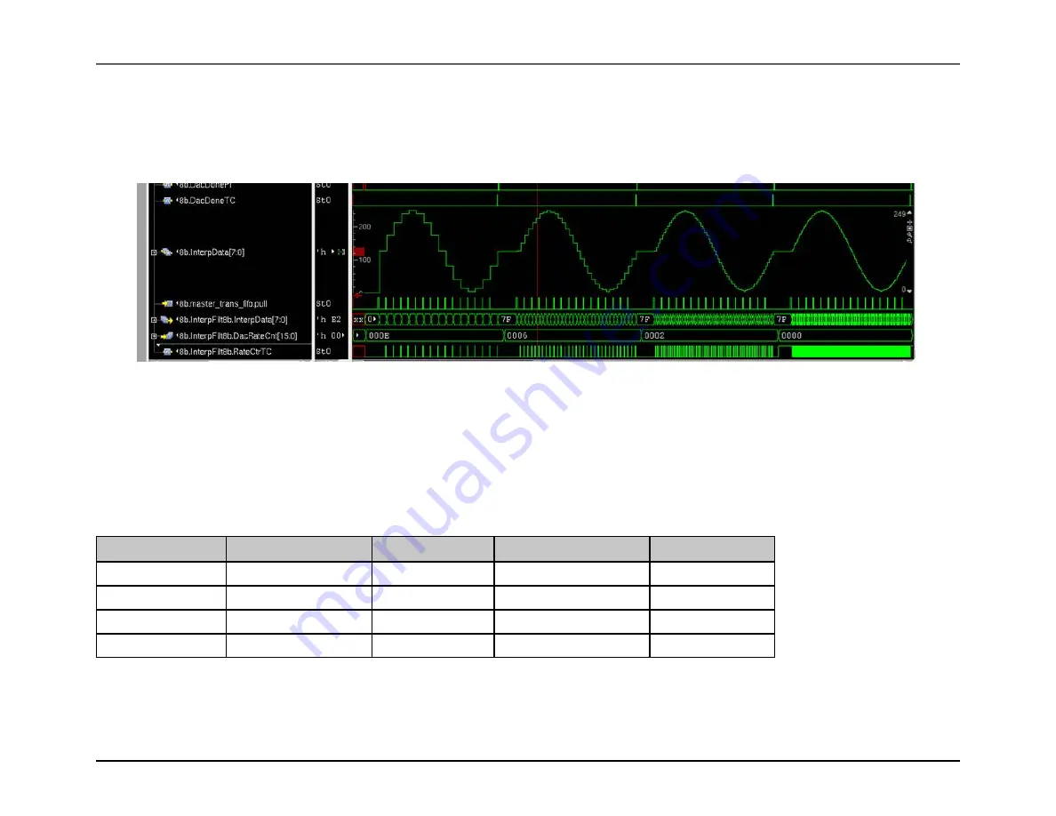
Increasing interpolation “smooths” the output waveform (as shown below, where the interpolation rate increases from left to right, but the additional data points
inserted may not be exactly accurate for the desired waveform. For the highest quality of the generated output waveform, the maximum number of true waveform
data points should be loaded via the DAC FIFO. Interpolation allows the bandwidth of data transfer into the DAC FIFO to be reduced (and possibly to reduce the
amount of computation that the application has to perform), but comes at a trade-off of a lower-quality wave output in most cases.
Figure 8.9: DAC Interpolation Waveform
If the output waveform is largely linear slopes (e.g., a triangle or sawtooth wave), then interpolated values may be equivalent to those that the application would have
calculated itself. In this case, interpolation can be used with no reduction in waveform quality.
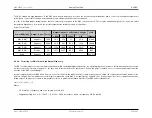
As mentioned above, the Rate Count parameter applies to output sample voltages after interpolation (if used) has taken place. Because increasing interpolation
increases the number of output samples, if this is not corrected for, the waveform output duration will increase proportionally. To fix this, the Rate Count must be
reduced when increasing interpolation in order to keep the same waveform output frequency, as in the example shown below.
Original Rate Count
Original rate_cnt value
Interpolation Used
New Rate Count Needed
New rate_cnt value
32
30
None
32
30
32
30
2-to-1
16
14
32
30
4-to-1
8
6
32
30
8-to-1
4
2
Rev.1.3 April 2015
Maxim Integrated
Page 458

