MAX32600 User’s Guide
System Configuration and Management
4.1 Power Ecosystem and Operating Modes
4.1.2
Low Power Modes (LP0: STOP and LP1: STANDBY)
Note
Low Power Modes LP0 and LP1 can only transition to/from LP3: RUN; to enter LP2: PMU from one of these modes, the device must first enter LP3:
Run.
4.1.2.1
Low Power Mode 0 (LP0: STOP)
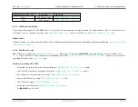
LP0: STOP is the lowest power mode supported by the
MAX32600
: using as little as 850nA in normal operation and as little as 1.25uA with the RTC active. The
core system registers and SRAM do not retain state and, upon exit from LP0: STOP, the system starts as if from a core reset. The sections of the
MAX32600
that
maintain state during LP0: STOP are:
• Power Sequencer
• Real-Time Clock (RTC)
• Data retention registers
• POR/Failsafe
4.1.2.2
Low Power Mode 1 (LP1: STANDBY)
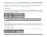
LP1: STANDBY is core data retention mode and supports fast wakeup time (
∼
15us typical) while maintaining ultra-low power. Typically, the
MAX32600
draws only
1.4uA in LP1: STANDBY without the RTC and only 1.8uA with the RTC enabled. All clocks are gated off, the core logic is in a static state, and the ARM is in deep
sleep. SRAM and registers have full data retention. Many options for analog support circuitry are available in this mode and, to achieve the lowest possible power in
LP1: STANDBY, it is recommended to turn off all unused analog circuitry. This includes the core 1.8V LDO because the Data Retention LDO is used to provide data
retention.
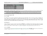
To achieve the 15us fast resume from LP1: STANDBY, a power-up sequence has been implemented. Instead of waiting for the 1.8V LDO voltage to become stable,
a gear shift mechanism is used that allows the core to run with a divided clock while the 1.8V LDO ramps and stabilizes; when the LDO is at a safe voltage, the
system shifts gears to the normal operating frequency.
Optional improvements to wakeup time can be achieved at the expense of burning more power. This may be appropriate for short periods of time in low power modes.
In this situation, continuous power consumption of run state is avoided, but extremely fast wake up times from a low power mode may be needed. To accelerate
the resume time, the 1.8V LDO and/or Relaxation Oscillator can be enabled during LP1: STANDBY. Power consumption during LP1: STANDBY will be higher, but
immediate resume times can be achieved under these conditions.
If the Relaxation Oscillator is not enabled during LP1: STANDBY, a 2us timeout is necessary due to waiting for the oscillator to stabilize prior to beginning code
execution.
Rev.1.3 April 2015
Maxim Integrated
Page 31

