MAX32600 User’s Guide
Analog Front End
8.5 LED
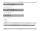
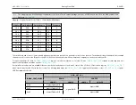
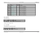
GPIO_OUT_VAL
DRAIN
SOURCE
IOMAN_CRNT_MODE
LOGIC 1
LOGIC 0
LOGIC 1
LOGIC 0
0x03
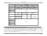
N-gate=OpAmp C/D
Feedback channel=Source
0x04
0x05
Reserved
0x06
0x07
N-gate=GND
N-gate=OpAmp C/D
N-gate=GND
P-gate=On
P-gate=Off
Feedback channel=Source
0x08
N-gate=OpAmp A/B
N-gate=GND
N-gate=GND
Feedback channel=drain
N-gate=GND
0x09
N-gate=OpAmp A/B
Feedback channel=Source
Feedback channel=drain
0x0A
0x0B
0x0C
Reserved
0x0D
0x0E
0x0F
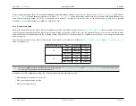
Note
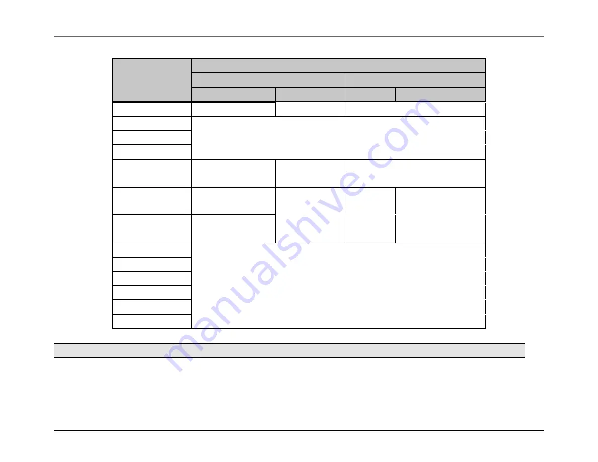
IOMAN_CRNT_MODE 0x7 is not available in the standard (12mm x 12mm) package.
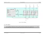
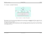
The feedback channel indicates which pad is connected to the I/O feedback channel. Which channel is connected depends on which I/O is used (the details are in
and
tables). Where not specified, the PMOS source is off and the feedback connection is floating.
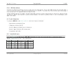
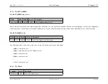
To operate the LED I/O in source mode, such as for H-bridge pullups or high voltage applications, the user must switch to digital high, with
0x9 (H-bridge) or 0x0 (high voltage). To switch between the modes, write
as above for the on state and
for the off
state; use
to switch between on and off.
Rev.1.3 April 2015
Maxim Integrated
Page 484

