MAX32600 User’s Guide
System Configuration and Management
4.1 Power Ecosystem and Operating Modes
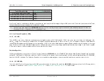
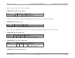
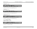
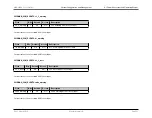
SVM Options for LP0 / LP1
Description
Enable Field
V
REG18
1.8V Regulated Output
V
RTC
3V VRTC Supply
4.1.7.3
SVM Periodic Monitoring
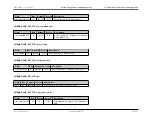
For periodic SVM during STOP or STANDBY modes, a clock source for the periodic timer should be enabled. The 8kHz oscillator or the RTC clock can be chosen
as the timer source. For the 8kHz nano ring, set the
bit; to use the RTC, set the
bit.
8kHz Oscillator
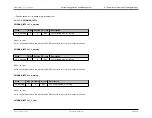
The 8kHz Oscillator is a low-power internal oscillator with a nominal frequency of 8kHz that allows periodic supply voltage monitoring during
4.1.7.4
First Boot Power Up
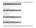
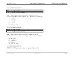
When initial power is applied, the
flag will be set to indicate the
MAX32600
is powering up from a first boot condition. The
register must be set to 0 by firmware prior to attempting to enter either
Low Power Modes (LP0: STOP and LP1: STANDBY)
. All power lost on the chip or
asserting RSTN will reset the
flag.
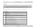
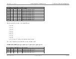
First Boot Up (entering LP3: RUN)
• Ensure pads are in the lowest power state by clearing the
register
• Clear I/O WUD on all pads by setting and clearing the
register
• Take all pads out of low power state by setting
to 1
• Deassert GPIO Freeze by setting
to 0
• Clear the first boot signal,
• Set the quick count bit in the the
to 1
• The
MAX32600
is in LP3: RUN
Rev.1.3 April 2015
Maxim Integrated
Page 39

