MAX32600 User’s Guide
System Clock, Timers/Counters, Watchdog Timers and Real Time Clock
10.3 Real Time Clock (RTC)
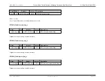
10.2.5.1.5
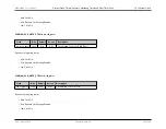
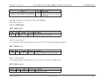
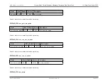
WDTn_LOCK_CTRL
WDTn_LOCK_CTRL.wdlock
Field
Bits
Default
Access
Description
wdlock
7:0
0 (POR only)
R/W
Lock for WDT CTRL Register
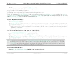
• If this field reads 0, the CTRL register may be written to.
• If this field reads 1, the CTRL register is read-only.
• Writing 0x24 to this field will set bit 0 to 1 (Lock).
• Writing 0x42 to this field will clear bit 0 to 0 (Unlock).
10.3
Real Time Clock (RTC)
10.3.1
Real Time Clock Overview
The Real Time Clock (RTC) on the
MAX32600
is designed to operate largely independent of other the digital and analog functions on the device. The RTC has its
own clock that runs off a 4kHz clock derived from the external crystal 32kHz oscillator output. While one of the main power supplies (V
DD
or V
BUS
) is active, the RTC
will run from that supply; however, it can automatically switch to run from the backup supply (V
RTC
) if the main supply powers down.
The RTC consumes very little power and can operate from its dedicated 4kHz clock base. It is, therefore, possible for the RTC to continue operating while the rest of
the
MAX32600
is in the lowest power saving mode,
. The RTC can be used to wake the device automatically from
after a
preprogrammed time interval (using the time of day alarm function). It can also be used to maintain a stable time value that continues to keep counting time properly
even when the rest of the system has been powered down or power has been removed entirely. As long as the backup supply V
RTC
is present, the Real Time Clock
can continue operating normally.
Note
Reference
for further information about
MAX32600
power modes.
10.3.1.1
Real Time Clock Features
The Real Time Clock on the
MAX32600
includes the following features:
Rev.1.3 April 2015
Maxim Integrated
Page 563

