background image


RMT55H


20195 South Diamond Lake Road, STE 100 

Rogers, MN 55374 

800.621-2789


28 


7


ADJUSTMENTS 

7.1


Clutch Adjustment 

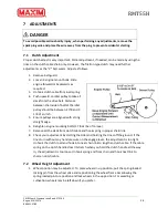
Proper clutch adjust is very important. Minor adjustment, if needed, can be made by using the 
links on the clutch cable chain only. However, the friction type clutch may need further 
adjustments as the “V” belt wears. Adjust as follows:   

1.


Remove belt guard. 

2.


Loosen 4 engine mount bolts. Slide 
engine forward or backwards as 
required. 

3.


Unhook clutch cable from load spring. 

4.


Push upward on idler pulley to take all 
slack from the drive belt. Distance 
between the inside of belt at the idler 
pulley should be between 2 7/8 and 3 
1/8 of an inch. 

5.


Ensure pulleys are aligned with a long 
straight edge. 

6.


Retighten engine mounting bolts (17 foot lbs. of torque). 

7.


Remove all the slack from clutch cable and hook spring in proper chain link. 

8.


Check your adjustment by starting the tiller and holding the tines off the ground. If the 
tines turn without any hand pressure on the engage lever, the adjustment is too tight. 
Unhook the clutch load and hook into next chain link to lengthen clutch cable. If the cable 
spring on the clutch handle doesn’t stretch when you hold the clutch handle all the way 
in, the adjustment is too loose. Unhook spring end from chain and hook next link to 
shorten clutch cable.  

7.2


Wheel Height Adjustment 

1.


Wheel position may be adjusted.  To place wheels in up position, pull the spring-loaded 
locking pin from the wheel yoke and repositioning the wheel frame bar allowing the 
spring-loaded pin to reposition and lock wheels in the up position. For weeding or 
cultivation, wheels may be left down if you prefer. 


DANGER 


To avoid possible serious bodily injury, when performing any adjustments, remove the 
spark plug wire and place the wire away from the plug to prevent accidental starting. 

Summary of Contents for MT PRO Series

Page 1: ...nual MRMT55HB WARNING USE EXTREME CAUTION WHILE USING THIS EQUIPMENT INJURY CAN OCCUR READ CAREFULLY AND UNDERSTAND ALL ASSEMBLY AND SAFE OPERATION INSTRUCTIONS BEFORE OPERATING FAILURE TO FOLLOW THE...

Page 2: ...Y 9 2 1 General Safety Rules 9 2 2 PRODUCT SPECIFIC SAFETY RULES 10 2 3 ENGINE SAFETY PRECAUTIONS 10 2 4 Safety Decals 14 2 5 Training 15 2 6 Preparation 15 2 7 Operation 15 2 8 Maintenance and Storag...

Page 3: ...27 7 ADJUSTMENTS 28 7 1 Clutch Adjustment 28 7 2 Wheel Height Adjustment 28 7 3 Tine Adjustment 29 8 Maintenance 29 8 1 Periodic Check 29 8 2 Engine Oil 29 8 3 Dual Filter Element Air Cleaner 30 8 4...

Page 4: ...ation must be included to make sure state laws and other laws are followed This manual should remain with the product even if it is resold WARNING THE ENGINE EXHAUST FROM THIS PRODUCT CONTAINS CHEMICA...

Page 5: ...bearing supports for increased durability Heavy duty tines with bolt on replaceable blades Heavy duty steel wheels Lift Handle Engine guard Heavy duty frame Lift handle and drag bar standard 1 3 Navi...

Page 6: ...e You will find important safety information in a variety of forms including 1 Safety labels on the tillers 2 Safety messages preceded by a safety alert symbol and one of the three signal words DANGER...

Page 7: ...pedestrian controlled but not self propelled with a gasoline fueled internal combustion engine to power the tines It shall not be used for any other purpose 1 5 Operation References Terminology Refer...

Page 8: ...local servicing dealer and more Your local dealer is equipped and trained to handle service and repair for your tiller 1 7 Model Identification Please fill in your model and serial number below for fu...

Page 9: ...rts Never wear sandals sneakers or open shoes and never operate the machine with bare feet Do not wear loose clothing or jewelry They can get caught in moving parts Always keep hands feet hair and loo...

Page 10: ...this machine 2 2 PRODUCT SPECIFIC SAFETY RULES Do not till above underground utilities including water lines gas lines electric cables or pipe Contact appropriate utility representatives to determine...

Page 11: ...es under tents car ports or basements Always run the engine with the exhaust pointed in the direction away from the operator Never point the exhaust towards anyone People should always be a minimum of...

Page 12: ...uel cap or add fuel with the engine running Stop engine and allow to cool before filling Do not smoke while using engine or around fuel Never drain fuel from engine in an enclosed area Always wipe up...

Page 13: ...r allow children to operate the machine Use extra care when approaching blind corners shrubs trees or other objects that may obscure vision SERVICE Always stop the engine whenever you leave the equipm...

Page 14: ...ty decals on the tiller to remind you of some of this important information while you are operating the unit These important safety decals are illustrated below and are shown here to help familiarize...

Page 15: ...worn whenever using the equipment 5 Handle fuel with care it is highly flammable 6 Use an approved fuel container 7 Never add fuel to a running engine or hot engine 8 Fill fuel tank outdoors with ext...

Page 16: ...5 Use only attachments and accessories approved by the manufacturer of the tiller 16 Never operate the tiller without good visibility or light 17 Be careful when tilling in hard ground The tines may c...

Page 17: ...ly Breakdown Ref Qty Part Description B 1 130761 Tine Assembly B1 16 80049 Bolt Hex 3 8 16 x 1 00 Zinc B2 16 86383 Nut Nylock 3 8 16 GR5 Zinc B4 4 130762 R H Slasher Blade 3554R HD Blk B5 4 130763 L H...

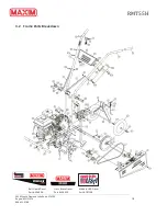
Page 18: ...th Diamond Lake Road STE 100 Rogers MN 55374 800 621 2789 18 3 2 Frame Parts Breakdown Cross Brace Decal Part 336919 Belt Guard Decal Part 336920 Made In USA Decal Part 797158 MT PRO SERIES rmt55h PN...

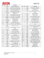
Page 19: ...ZINC 15 1 500003 R H FRAME RAIL 17 1 130400 TRANSMISSION COMPLETE PAINT 18 1 162069 IDLER SHAFT TILLER 19 1 338009 IDLER PULLEY 2 3 4 X 3 8 Ref Qty Part Description 20 2 359335 SPACER TRANS FORM 7 8 2...

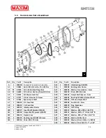
Page 20: ...38 Output Shaft Sprocket 50A22 A12 1 336675 Gasket Case A13 2 359293 Bushing Input AA811 Bronze A14 1 359296 Chain 35 X 70 Links Ref Qty Part Description A15 2 359297 Idler Bearing SCH912 A16 1 359298...

Page 21: ...2 Take out all unassembled parts parts bag and protective packing and safety maintenance manuals 3 Install tine assemblies on shaft using 4 tine pins and 4 cotter hair pins Be sure that all cutting ed...

Page 22: ...ission to ensure that it has the proper amount of lube a Remove check plug b Use 90 wt gear lube Approx 1 pt c Fill until check plug hole overflows d Replace plugs NOTE do not overtighten 2 Remove the...

Page 23: ...and fill according to the engine owner s manual WARNING Engine is shipped from factory without oil You must add engine oil before starting engine If engine is started without oil engine may be damaged...

Page 24: ...plug wire for proper connection on the spark plug 2 Fill the fuel tank with clean fresh regular gasoline from a sealed container 3 Check the oil for proper level 4 Make certain clutch lever is in dise...

Page 25: ...e start of the compression cycle the rope will pull slightly harder at this point Then allow the rope to retract fully 3 Pull the rope with a continuous full arm stroke Keep a firm grip on the starter...

Page 26: ...lt and tines while engine is running WARNING For safe operation the chain drive must disengage immediately when clutch lever is released If it does not adjust belt and cable tension as described in Se...

Page 27: ...sure you put on the drag stake Do not fight the tiller Stand between the handles and press down to go slower and dig deeper and release the downward pressure to move forward faster In normal soil the...

Page 28: ...nd hook spring in proper chain link 8 Check your adjustment by starting the tiller and holding the tines off the ground If the tines turn without any hand pressure on the engage lever the adjustment i...

Page 29: ...d after every five hours of operation 2 Be sure engine is cool 3 Before removing the filer plug clean the area around it to prevent dirt from entering the oil fill hole 4 The engine should be in a lev...

Page 30: ...ooling system after prolonged service Continued operation with a clogged cooling system causes severe overheating and possible engine damage 8 5 Belt Replacement The drive belt located on the left sid...

Page 31: ...emely dusty conditions wheels may become tight because of dust in bearing area When this condition occurs remove the wheels Clean axle and wheel bearing surfaces with solvent or emery cloth then oil a...

Page 32: ...ler is to be stored for any length of time it should be cleaned following the cleaning instructions in Section 8 6 11 TRANSPORTING To transport tiller from garden to storage area 1 Move the throttle c...

Page 33: ...your product immediately after purchase You can do that by visiting our website at www maximmfg com and complete our online product registration Or complete the following warranty production registra...

Page 34: ...RMT55H 20195 South Diamond Lake Road STE 100 Rogers MN 55374 800 621 2789 34 Or Fax completed form to 763 428 4821...

Page 35: ...RMT55H 20195 South Diamond Lake Road STE 100 Rogers MN 55374 800 621 2789 35...

Page 36: ...RMT55H 20195 South Diamond Lake Road STE 100 Rogers MN 55374 800 621 2789 36...

Reviews: