- 8 -
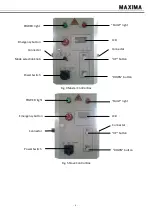
5.1.5. Emergency button
When you press this switch, no operation is available immediately. There is one emergency
button on each control box.
It must be released before lift operation. Then turn on the power switch.
5.1.6. Operation button
“UP” button: Press and hold this button, the carriages will rise.
“DOWN” button: Press and hold this button, the carriages go down to the required height after
system unlocking the hooks automatically.
5.2. Instruction
Working voltage: DC 24V Battery;
Working temperature: 42 ~ 104
o
F;
Working humidity: 50%@104
o
F -90%@68
o
F;
Working altitude: ≤1000m;
Circuit inside control box is forbidden to disassemble or maintenance without permission;
Noise: ≤75dB(A);
6. Debugging
6.1. Power supply
The power supply is 24V Battery;
6.2. Battery charge
Please charge the column when “Please charge battery” occurs onto the screen. The charging
voltage is: AC 220V, 1 phase
6.3. Test process
6.3.1. Single column test
Power on: Connect all 4/6 columns with communication cable, turn the Mode Selection knob
to SINGLE, and power on main column and all slave columns. LCD screen will show work
interface after successful connection.
Rise: Unloaded, press and hold the “UP” button on the master control box, check if the carriage
rises normally. Repeat to try the other columns in same way.
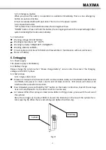
Air release: When the carriage is crawl and wobble in lifting process, please vent the air out of
the cylinder.
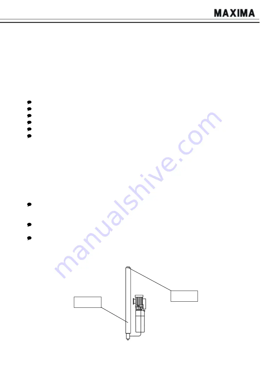
Raise the carriages up to about 600mm; loosen the Drain-tap on the top of the cylinder two
turns (see Fig. 8). When there is oil coming out, tighten the Drain-tap.
Cylinder
Drain tap
Fig. 8
Summary of Contents for ML4030B
Page 1: ...MAXIMA HEAVY DUTY COLUMN LIFT ML4030B ML6045BUSER MANUAL ...
Page 14: ... 12 Addendum 1 Hydraulic valve ...
Page 16: ......


