5-10t Internal Combustion Counterbalance Forklift Truck Operation & Maintenance Manual
-71-
5.3.1 Vacuum Booster and Brake Master Cylinder
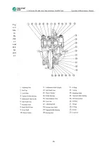
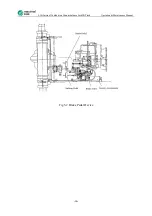
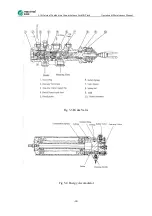
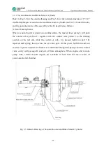
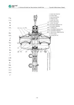
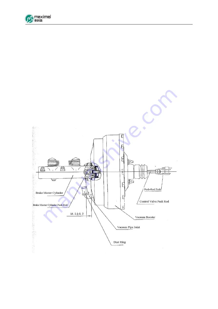
Refer to Fig 5-5 for the outside drawing and Fig 5-6 for the internal structure of 9’’+10’’
double-diaphragm vacuum booster and brake master cylinder used for 5-7t forklift trucks,
and the operating status of the assembly is briefly described as follows:
(1)Non-Working Status
When vacuum booster is under non-working status, the tapered large spring 3 will push
the control valve push rod 1 together with the control valve piston 5 to the limiting
position on the rear end, while the control air valve 4 is pressed tightly on part 5 by
tapered small spring, thus to close the air valve port. At this point, both front and rear
cavities of power-assisted air chamber are interlinked through the passage and the control
valve cavity with passage B, and cut off from atmosphere. When engine and vacuum
pump work, certain vacuum degrees are available in both front and rear cavities of
power-assisted air chamber.
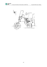
Fig 5-5 Outside Drawing of Vacuum Booster and Brake Master Cylinder
Summary of Contents for FD100T
Page 12: ...5 10t Internal Combustion Counterbalance Forklift Truck Operation Maintenance Manual 12 ...
Page 15: ...5 10t Internal Combustion Counterbalance Forklift Truck Operation Maintenance Manual 15 ...
Page 63: ...5 10t Internal Combustion Counterbalance Forklift Truck Operation Maintenance Manual 63 ...
Page 65: ...5 10t Internal Combustion Counterbalance Forklift Truck Operation Maintenance Manual 65 ...

