5-10t Internal Combustion Counterbalance Forklift Truck Operation & Maintenance Manual
-73-
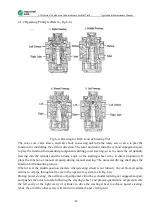
(2)Brake Working Status
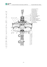
A. When brake pedal is just pushed down, the pedal force acts on the control valve stem 1
through lever amplification, and compresses part 3, to move forward together with part 5.
Through action of the feedback disc 10 and the master cylinder push rod 13, certain pressure
is generated inside the brake master cylinder and transmitted to the brake wheel cylinder
inside the brake wheel, and at the same time, the control air valve 4 moves forward with part
5 under the action of small tapered spring 6, to get contact with the port of vacuum valve on
the control valve body 7, and close it, for the two front and rear cavities of power-assisted air
chamber to be separated from each other (namely the rear cavity of power-assisted air
chamber is disconnected with the vacuum source.).
B. Along with the further forward movement of the control valve push rod 1, the control valve
piston 5 leaves the part 4, and the external atmosphere is filled into the rear cavity of
power-assisted air chamber through the air filter gasket as well as the control valve cavity and
the passage B, thus most of the forward acting force caused by air pressure difference in the
two cavities of power-assisted air chamber is effected on the feedback disc, and transmitted to
the brake master cylinder, to play the power assisting function, through the control valve body
7, except a small part of the action force used for balancing the action force of the large
tapered spring 3.
3. Brake Process Termination, and Recovery to Non-Working Status
A. In the process when brake pedal is pushed (namely the forward movement of the control
valve push rod), air continuously enters into the front and rear cavities of power-assisted air
chamber through the opened air valve port, and the control valve body keeps moving forward.
When brake pedal stops being pushed and stays at certain position, the control valve body
also moves forward and stops at the position where the air valve port is closed. At this point,
the vacuum valve port and the air valve port are both closed, the booster is under the balanced
status, namely a balanced status is maintained among the three including the air pressure
difference between the front and rear cavities of power-assisted air chamber, the pressure of
oil pressure for brake master cylinder, and the thrust of the control valve push rod, and the
wheel brake is under the braked status.
B. When brake pedal is released, the control valve push rod 1 and the control valve piston 5
are immediately pushed rearwards under the effect of return spring 14 and large tapered
spring 3, for the control air valve 4 to be disengaged from the vacuum pump port, and then a
braking process is completed, and it recovers to the original non-working status.
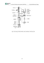
5.3.2 Method for Installation of Vacuum Booster and Brake Master Cylinder Assembly
(1)Connect the 4-M8 bolts for the booster with the mounting bracket and mount it on the
frame of forklift truck. Connect the adjusting fork on the end part of booster with the
connecting rod of brake pedal. Then tighten the 4-M8 bolts, at a tightening torque of
12N.m-18N.m.
(2)Connect the vacuum hose onto the joint of vacuum pipe for the booster, and keep it sealed.
(3)Connect the brake oil pipe with the 2-M10x1 thread for the oil outlet of brake master
cylinder, at a tightening torque of 12 N·m-18 N·m.
(4)Open the turning lid of liquid storage room, and inject the brake fluid (not to be blended
with dust or impurity). Exhaust the air inside the entire brake system.
Summary of Contents for FD100T
Page 12: ...5 10t Internal Combustion Counterbalance Forklift Truck Operation Maintenance Manual 12 ...
Page 15: ...5 10t Internal Combustion Counterbalance Forklift Truck Operation Maintenance Manual 15 ...
Page 63: ...5 10t Internal Combustion Counterbalance Forklift Truck Operation Maintenance Manual 63 ...
Page 65: ...5 10t Internal Combustion Counterbalance Forklift Truck Operation Maintenance Manual 65 ...

