background image


3  Safety instructions 

MAXIMATOR  compressors  are  manufactured  to  the  latest  state  of  the  art  and  are 
safe  to  operate.  However,  there  are  potential  hazards  in  case  of  inadvertent  wrong 
operation or wrong use: 

• 

For the health and lives of persons. 

• 

For the compressor and its accessory parts as well as other assets. 

• 

For the life cycle and the performance capacity of the compressors and its 
accessory parts. 

 
Operation,  maintenance  and  assembly  of  the  compressor  may  only  be  carried  by 
personnel who are familiar with working on pneumatic systems and are familiar with 
the hazards entailed by such systems. In addition, the operating instructions shall be 
thoroughly studied and adhered to. 


3.1  Usage to the intended purpose 

The  compressors  may  be  exclusively  used  with  those  media  for  which  they  are 
suitable  according  to  our  media  endurance  schedule.  Any  other  media  have  to  be 
tested by us for compatibility with the compressor materials prior to being used. The 
compressor drives are designed for compressed air up to 10 bar, other gases have to 
be tested by us for compatibility with the compressor materials prior to being used.  
 
Changes and modifications of the compressors are prohibited for safety reasons. 
 
All  maintenance,  assembly  and  operating  instructions  specified  in  these  operating 
instructions must be adhered to in order to guarantee full functioning and safety.  
 

3.2  Emission 

Expanding  compressed  air  is,  depending  on  the  specific  application,  prone  to 
generate a certain level of noise. Moreover, exhausting air from the silencer may be 
fouled with water and oil (grease). It is also possible that small ice crystals form at the 
silencer,  become  loose  and  fly  around.  This  is  why  persons  have  to  wear  goggles 
and, if need be, ear protection while in the vicinity of running compressors. 


3.3  Safety hazards 

During operation of the unit, both the drive part and the high-pressure part are under 
pressure.  Hence,  it  should  be  borne  in  mind  that  any  gas  that  may  leak  due  to  a 
defect  or  also  during  normal  operation  are  highly  pressurised  and  must  not  be 
contained or deviated by objects or body parts. It must be ensured that in case of a 
defect a compressor is immediately depressurised and repaired. 
 
Maintenance and repair work may only be carried out at depressurised units.  


Summary of Contents for DLE 5

Page 1: ...g maintenance and repair instructions for MAXIMATOR Compressors DLE 5 MAXIMATOR GmbH Walkenrieder Straße 15 37449 Zorge Phone 49 55 86 80 30 Fax 49 55 86 8 03 40 E Mail Info maximator de Homepage www maximator de ...

Page 2: ...______________ 8 5 3 1 Inlet ___________________________________________________ 8 5 3 2 Pressure line ____________________________________________ 8 5 3 3 Pumping medium ________________________________________ 8 5 4 Operation __________________________________________________ 8 6 Maintenance ___________________________________________________ 9 7 Warranty ________________________________________...

Page 3: ...rger effective surface area than in the control chamber that is permanently impinged with compressed air The HP piston generates the volume flow by means of check valves suction valve delivery valve 1 The HP section of the compressors consists of two stages The first stage has a low pressure ratio and conveys directly into the second stage with a high pressure ratio These two stages allow for the ...

Page 4: ...have to be tested by us for compatibility with the compressor materials prior to being used Changes and modifications of the compressors are prohibited for safety reasons All maintenance assembly and operating instructions specified in these operating instructions must be adhered to in order to guarantee full functioning and safety 3 2 Emission Expanding compressed air is depending on the specific...

Page 5: ...age The air drive has been designed in such manner that the compressors are safe to be operated in areas that subject to explosion hazards The compressor should be installed in such a manner that the operating elements and bolted connections are freely accessible at any time 4 Technical data Type Pressure ratio Compression ratio Admission pressure Min Max Max operating pressure Turn of piston volu...

Page 6: ...6 ...

Page 7: ...nt o 10 C water content 9 4g m up to 2 C water content 5 6g m 5 2 2 Compressed air oiler As a rule a compressed air oiler is not required All moving parts have been treated with special grease during assembly The grease may become gummy when the compressor is operated for a longer period of time with extremely dry air It is recommended to replace the compressed air oiler in such a case Caution If ...

Page 8: ... connections are not suitable A filter with a mesh width of max 10µm should be installed into the suction line to avoid damage at the suction and delivery valves as well as at the HP sealing 5 3 2 Pressure line The pressure line and the respective accessories must withstand the max initial pressure of the compressor It is recommended to install an appropriate safety valve into the pressure line 5 ...

Page 9: ...ailable from MAXIMATOR as spare parts The respective purchase order numbers can be gathered from the drawings attached to each compressor Typically there is more than one sealing defective or worn out hence we have compiled different sealing kits The compositions of sealing kits can be gathered from the drawings like the respective purchase order numbers Make sure to indicate the compressor serial...

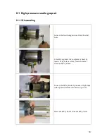
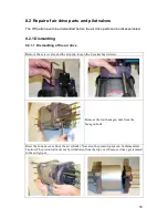
Page 10: ...our hexagon nuts from the stud bolts Carefully separate the compressor head by means of light taps with a plastic hammer from the HP cylinder Loosen the HP cylinder by means of light taps with a plastic hammer from the top cover Draw the HP cylinder from the HP piston ...

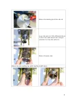
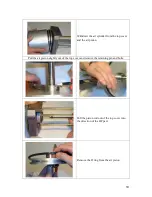
Page 11: ... of the castle nut Loosen the castle nut If the HP piston follows to turn it is recommended to use an impact screwdriver to loosen the castle nut Remove the piston disk Remove the piston sealing ring and O ring from the HP piston ...

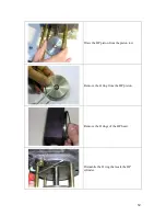
Page 12: ...12 Draw the HP piston from the piston rod Remove the O ring from the HP piston Remove the O rings of the HP head Dismantle the O ring that seals the HP cylinder ...

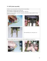
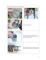
Page 13: ... sealing and guide elements Use preferably MAXIMATOR grease Works No 3610 1456 Grease the top and bottom cover the O rings that seal the HP part and assemble the rings first and second stage Attach the HP piston to the piston rod Grease the O ring and insert it into the groove between HP piston and piston rod ...

Page 14: ...e HP piston Grease the HP cylinder Insert the piston sealing ring into the HP cylinder and align the ring parallel ca 13 mm below the cylinder edge Push the HP cylinder over the HP piston until the piston sealing ring fits close to the O ring ...

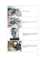
Page 15: ...g lock washer and the castle groove Tighten the castle groove with 25 Nm The piston sealing ring is pushed onto the O ring during tightening Use the retaining pin to secure the castle nut appropriately bend the retaining pin with a screwdriver ...

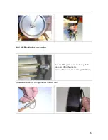
Page 16: ...16 8 1 3 HP cylinder assembly Push the HP cylinder over the O ring of the top cover till to the stopper Caution Make sure not to damage the O ring Grease and mount the O rings that seal the HP head ...

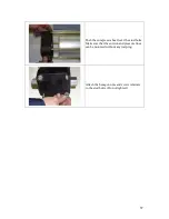
Page 17: ... Push the compressor head over the stud bolts Make sure that the suction and pressure lines can be mounted without any warping Attach the hexagon nuts and screw retainers to the stud bolts Do not tighten ...

Page 18: ... 1 1 Dismantling of the air drive Remove the servo valve and the air pipe loosen the 4 socket head screws Remove the four hexagon nuts from the hexagon bolts Draw the bottom cover from the air cylinder Now also the pressure pipe can be dismantled Caution The piston rod must not be withdrawn from the top cover because it may get jammed in the end groove ...

Page 19: ... the top cover and the air piston Pull the air piston slightly out of the top cover and remove the retaining pin and bolts Pull the piston rod out of the top cover into the direction of the HP part Remove the O ring from the air piston ...

Page 20: ...cover and bottom cover Remove the locking ring Knock the bearing bush out of the top and bottom covers by means of a plastic mandrel Remove the O rings from the bearing bush Remove the sliding rings and O rings from the bearing bush ...

Page 21: ...tle the O ring that seals the air cylinder Dismantle the O rings for the control pipe from the top and bottom covers Remove the O rings from the pressure pipe Loosen completely and unscrew the pilot valve screw ...

Page 22: ...the USIT ring compression spring and pilot valve tappet Turn the top cover round in order to lever out the serrated ring washer and O ring by means of a small screwdriver The components are destroyed in the process ...

Page 23: ...85 Slip the serrated ring washer and O ring in this order onto the centring mandrel When attaching the serrated ring make sure that the serration points away from the O ring To begin with insert the centring mandrel into the tappet boring Then drive the entire package with some hammer strokes into the boring Caution Make sure that the O ring is fully attached to the bottom Wedging mandrel Centring...

Page 24: ...tappet During assembly a tangible resistance must be felt from the previously mounted O ring Slip the compression spring onto the pilot valve tappet Insert the USIT ring into the boring Then tighten the pilot valve screw with a torque of 25Nm ...

Page 25: ...g against slipping out Upset the boring with a few hammer strokes Insert the O ring into the bearing bush Form the sliding ring into a kidney shape and insert it Subsequently bring the sliding ring inside the groove back into its original form Caution Do not bend the sliding ring too sharply ...

Page 26: ...ter of the bushing Grease the boring in the cover and insert the bushing with pressure Caution Make sure not to inadvertently remove the O rings Insert the locking ring into the foreseen groove Check also for its correct seat Mount the O ring that seals the air cylinder ...

Page 27: ... 8 2 2 2 Air drive assembly Grease the bearing bush of the bottom cover Insert the air piston with piston rod into the bottom cover Grease and attach the O ring for the air piston Grease the air cylinder ...

Page 28: ...om cover together until the air cylinder fits closely to the bottom cover Carefully move the piston rod from outside through the greased bearing bush of the top cover Caution Make sure not to damage the sliding rings in the bearing bush in the process Insert the piston rod into the piston rod holder of the air pistons and fasten with the pin ...

Page 29: ... into the top and bottom covers and use the capillary control tube to push the O ring into the boring till to the stopper Slightly push the top and bottom cover together and insert the capillary control tube Carefully push the air drive part together until the air cylinder fits closely to the top cover ...

Page 30: ...rked with PL Also on the opposite side the fastening brackets screw retainers and washers are pre assembled together with the hexagon nuts Tighten the bolts only slightly The DLE is placed on a workbench for alignment and a soft hammer is used to align the top and bottom cover in parallel Then tighten the hexagon nuts crosswise with the specified torque of 55 Nm ...

Page 31: ...31 Grease and slip on the O rings for the air pipe Re attach the servo valve with cooling tube and the air pipe check the correct seat of the O rings ...

Page 32: ...ery valves 8 3 1 Dismantling 8 3 1 1 Suction valve Loosen the inlet sockets Pull out the entire valve unit by means of the inlet socket Use a mandrel to force the valve unit out of the inlet socket Remove the O ring from the valve seat ...

Page 33: ...t socket The main parts of the suction valve are Inlet socket valve ball spring ball holder valve seat and two O rings 8 3 1 2 Delivery valve Loosen the outlet sockets The ball and spring fall out and the valve seat stays in the HP head ...

Page 34: ... Use a mandrel to force out the valve seat that is still in the HP head Remove the O ring that seals the valve seat Force the ball holder out of the outlet socket Remove the O ring from the outlet socket ...

Page 35: ...re Inlet socket valve ball spring ball holder valve seat and two O rings 8 3 2 Assembly 8 3 2 1 Outlet valve Grease the O ring and slip it onto the outlet socket Grease the O ring that seals the valve seat and insert the ring in to the HP head ...

Page 36: ...36 Use a cone shaped mandrel to force the valve seat into the HP head Insert the ball into the valve seat Attach the spring on to the ball Push the ball holder over the spring ...

Page 37: ...sure to check before the correct seat of the ball and the spring Tighten the outlet socket with 120 Nm 8 3 2 2 Inlet valve Grease the O ring and slip it onto the inlet socket Grease the O ring that seals the valve seat and slip it onto the valve seat ...

Page 38: ...and the ball onto the inlet socket and carefully press them into the socket Place the spring on top of the ball Slip the ball holder over the spring Screw the inlet socket into the HP head Tighten the inlet socket with 120 Nm ...

Page 39: ...pipes are only loosely pushed in and can smoothly be withdrawn from the spool valve housing and the intermediate cover Remove the O rings that seal the top cover Dismantle the locking ring at the spool valve housing with suitable locking ring pliers The ring is located opposite the compressed air inlet ...

Page 40: ...re statically sealing i e they are not subject to wear and tear This means that the spool valve sleeve has only to be dismantled when it is damaged Use a mandrel to force the spool valve sleeve out of the spool valve housing Caution Make sure to avoid damaging the spool valve sleeve Preferably use a plastic or wooden mandrel with an appropriate diameter Remove the O rings from the spool and if app...

Page 41: ... 8 4 2 Assembly Check all components for damage and replace them as required There must not be any scoring at the spool valve sleeve Grease all O rings Slip the O rings onto the servo valve sealing cap and if applicable the spool valve sleeve ...

Page 42: ...with rotating motions into the spool valve sleeve If applicable grease the spool valve housing internally and install the spool valve sleeve with slight rotating motions into the spool valve housing Re insert the sealing cap into the spool valve housing and fasten it with the locking ring ...

Page 43: ...ling between spool valve housing and top cover into the O ring nests Re attach the spool onto the DLE During the process guide the air pipes into the spool valve housing Place the 4 socket head screws to fasten the spool valve housingand tighten the screws with 5 Nm ...

Reviews: