VP30/VP500
MAINTENANCE INFORMATION
Blowing safety Valves
Possible reasons for safety valves blowing are given below. In addition to these reasons, it may be
possible that the safety valves themselves can be faulty. Safety valve adjustments may change
due to vibration, or the valve may be worn.
In general, the normal operating pressures of the three stages of the compressor will be as follows:
1st stage: up to 21 Bar
2nd stage: up to 97 Bar
3rd stage: up to 350 Bar
If a safety valve is blowing below the pressures given above for each stage, then it is likely that the
valve requires adjustment or replacement.
Note: It is extremely dangerous to adjust safety
valves pressures without the correct equipment. Replacement is recommended.
Crankcase breather safety valve blowing
1st stage cylinder head gasket damaged. Check and replace.
1st stage suction valve faulty. Check and clean/replace.
1st Stage safety valve blowing
2nd stage cylinder head gasket damaged. Check and replace.
2nd stage suction valve faulty. Check and clean/replace.
2nd Stage safety valve blowing
3rd stage concentric valve and/or seals worn or damaged. Check and clean/replace.
3rd Stage safety valve blowing
Outlet Check Valve or outlet pipes blocked. Check and Clean/Replace
Leakage from HP receivers
If the pressure in the HP receivers or pipework reduces, even when no gas is being consumed, it is
possible that the compressor outlet check valve is faulty and that gas is leaking back through it and
to the unloader vent, when the compressor is not running. Check and replace check valve.
Low oil pressure
Low oil level - Check and refill oil pump suction strainer fitted to drain plug 2/15 is clogged. Drain
the compressor oil and clean the strainer. Use compressed air to blow away any dirt, from the
inside of the strainer.
Knocking
Hard metallic knocking noises normally indicate worn crankpin journals or big end bearings. If the
crankpin journals are excessively worn, the crankshaft 3/1 must be replaced. If the wear is minor,
the connecting rods 4/1 (3 pcs) may be replaced.
July 21
13 of 42
Summary of Contents for VP30
Page 15: ...VP30 VP500 MAINTENANCE INFORMATION Fig 2 Crankcase July 21 15 of 42 ...
Page 17: ...VP30 VP500 MAINTENANCE INFORMATION Fig 3 Crankcase July 21 17 of 42 ...
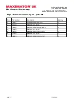
Page 19: ...VP30 VP500 MAINTENANCE INFORMATION Fig 4 Piston and connecting rod July 21 19 of 42 ...
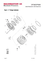
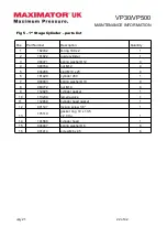
Page 21: ...VP30 VP500 MAINTENANCE INFORMATION Fig 5 1st Stage Cylinder July 21 21 of 42 ...
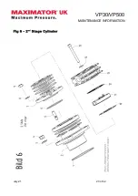
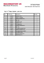
Page 23: ...VP30 VP500 MAINTENANCE INFORMATION Fig 6 2nd Stage Cylinder July 21 23 of 42 ...
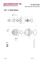
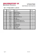
Page 25: ...VP30 VP500 MAINTENANCE INFORMATION Fig 7 3rd Stage Cylinder July 21 25 of 42 ...
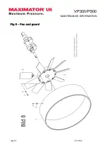
Page 27: ...VP30 VP500 MAINTENANCE INFORMATION Fig 8 Fan and guard July 21 27 of 42 ...
Page 29: ...VP30 VP500 MAINTENANCE INFORMATION Fig 9 Coolers July 21 29 of 42 ...
Page 31: ...VP30 VP500 MAINTENANCE INFORMATION Fig 10 Unloader Manifold July 21 31 of 42 ...
Page 34: ...VP30 VP500 MAINTENANCE INFORMATION Fig 11 Unloaders July 21 34 of 42 ...
Page 36: ...VP30 VP500 MAINTENANCE INFORMATION Fig 12 Oil Lubrication July 21 36 of 42 ...
Page 38: ...VP30 VP500 MAINTENANCE INFORMATION Fig 13 Crankcase Breather July 21 38 of 42 ...
Page 40: ...VP30 VP500 MAINTENANCE INFORMATION Fig 14 Motor July 21 40 of 42 ...


