10
11
model no. 054-7291-6 | contact us 1-888-670-6682
®
INSTALLING AND REMOVING SANDING BELTS (FIG. A)
TO INSTALL BELT:
• Place sander on its side and pull the belt tension release
lever out.
• Insert the new belt around both rollers, and make sure the
arrow on the inside of belt corresponds to the direction of
rotation as indicated on housing.
• Once the belt is centred over the rollers and bottom plate,
push lever back to its original position to return tension to
the belt.
TO REMOVE BELT:
• Place sander on its side and pull the belt tension release lever out.
• With the sander on its side and the open side facing you, you can easily remove the
belt.
ADJUSTING BELT TRACKING (FIG. B)
This sander features an automatic tracking system designed to keep the sanding belt
centred. The system has been preset at the factory but may require adjustment when
belts are changed or an older belt stretches. For best performance the belt should be in
line with the outer edge of the rear pulley. If the belt deviates more than 1/8” (3.2 mm)
from the outside of the sander, adjust the belt position.
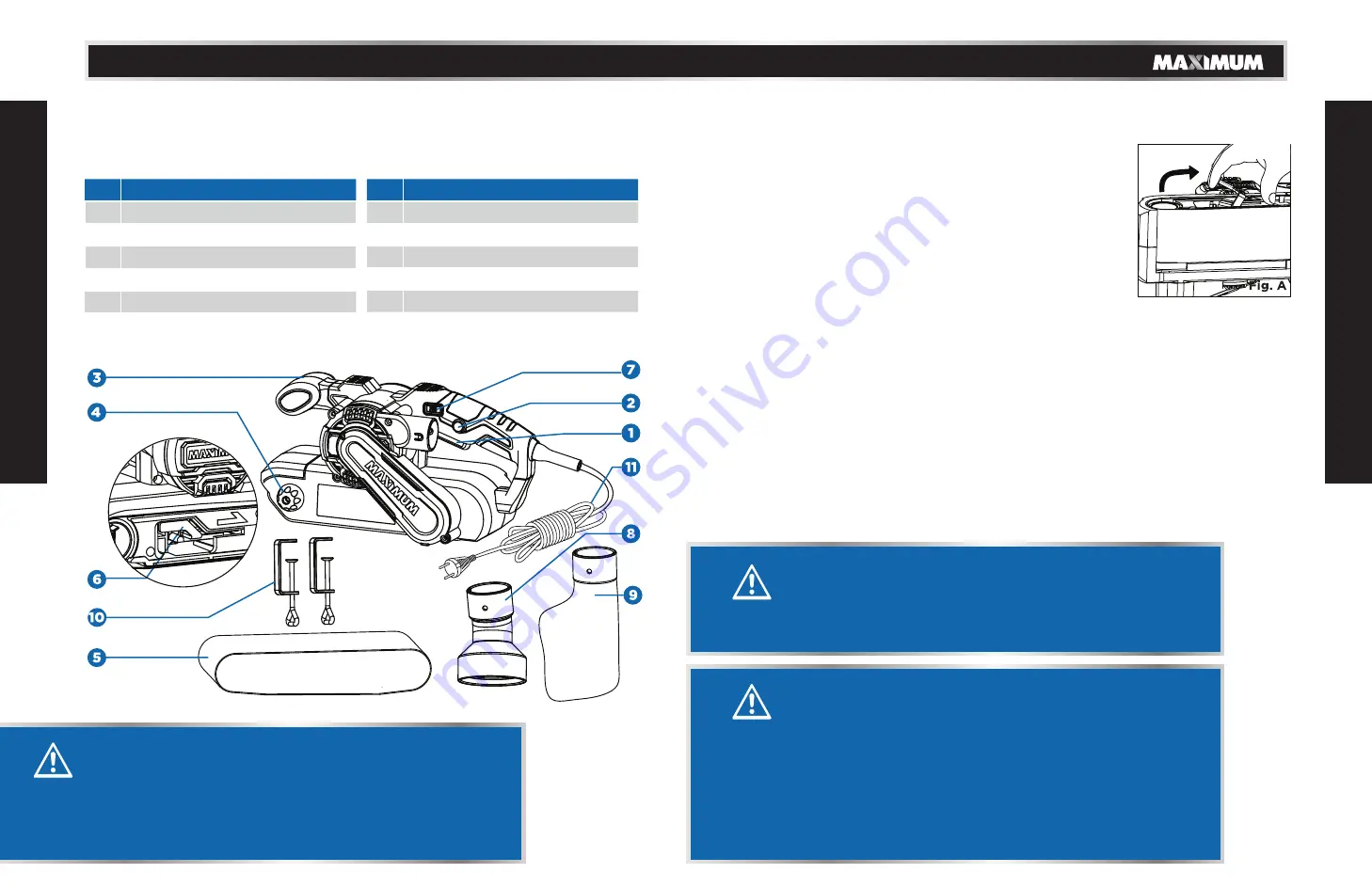
KEY P
ART
S DIA
GR
AM
No. Description
1
ON/OFF trigger
2
“Lock-on” button
3
Front handle
4
Belt adjustment knob
5
Sanding belt
6
Belt tension release lever
No. Description
7
Variable speed control dial
8
2-in-1 Vacuum adaptor
9
Dust collection bag
10
Fixing clamp
1 1
Power cord and plug
A
S
SEMBL
Y INS
TRUCTIO
NS
WARNING!
• Remove the product and any accessories from the
package. Inspect the tool carefully to make sure no
breakage or damage occurred during shipping.
• Do not discard the carton or any packaging material
until all parts have been examined.
PACKAGE CONTENTS
Belt sander, 1 pc sanding belt (fixed on the tool), 1 pc 2-in-1 vacuum adaptor, 1 pc dust
bag, 2 pcs fixing clamps and instruction manual.
WARNING!
To prevent personal injury, disconnect the sander from the
power source before making adjustments or assembling
accessories.
WARNING!
• Keep hands and fingers away from moving sanding belt. Any
body part coming in contact with moving sanding belt could
result in serious injury. Do not wear loose clothing or jewellery
when operating sander. They could get caught in moving
parts and foreign objects could get thrown from sander
causing injury.
• Do not allow familiarity with products to make you careless.
Remember that a careless fraction of a second is sufficient to
inflict serious injury.
Summary of Contents for 054-7291-6
Page 1: ......
Page 12: ...model no 054 7291 6 contact us 1 888 670 6682 22 WARRANTY...
Page 13: ......


