maxon motor control
3-12
Document ID: rel2895
MCD EPOS P Programmable Compact Drive
Edition: December 2011
MCD EPOS P 60 W Hardware Reference
© 2011 maxon motor. Subject to change without prior notice.
Remark
Valid for T
a
= 25°C, thermally isolated, no convection, 5000 rpm.
Higher values (I
cont
max.3 A) are possible under more favorable ambient conditions, such as…
• free convection or forced air cooling
• thermal coupling
• lower speed
Table 3-5
Electrical Data – Inputs
Table 3-6
Electrical Data – Outputs
Table 3-7
Electrical Data – Interfaces
Table 3-8
Electrical Data – Memory
Table 3-9
Electrical Data – LEDs
Inputs
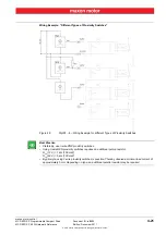
Digital Input 1 (“General Purpose”), optically isolated
+9…+24 VDC
Digital Input 2 (“Home Switch”), optically isolated
+9…+24 VDC
Digital Input 3 (“Positive Limit Switch”), optically isolated
+9…+24 VDC
Digital Input 4 (“Negative Limit Switch”), optically isolated
+9…+24 VDC
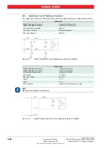
Digital Input 7 (“High Speed Command”)
internal line receiver EIA RS422 Standard
Digital Input 8 (“High Speed Command”)
internal line receiver EIA RS422 Standard
+V Opto IN
+12…+24 VDC
Outputs
Digital Output 3 (“General Purpose”), optically isolated
max. 24 VDC (I
L
<350 mA)
Digital Output 4 (“General Purpose”), optically isolated
max. 24 VDC (I
L
<350 mA)
Interfaces
RS232
RxD; TxD
max. 115 200 bit/s
CAN
CAN_H (high); CAN_L (low)
max.1 Mbit/s
CAN ID
no mechanical switch, configured according to LSS CiA DSP-305
Memory
Total memory
512 kByte
Application memory (free programmable)
256 kByte
Non-volatile memory
512 Byte
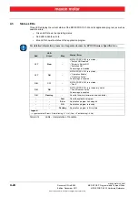
Status Indicators
Bicolor LED
green = ENABLE, red = FAULT
Blue LED
PROGRAM STATUS


