background image


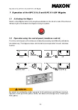
Operation of the GPC X1-LD and GPC X1-LDF liftgates 


22 

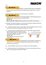
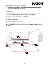
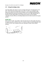
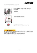
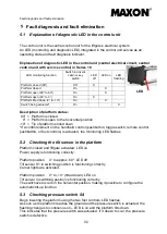
3.4.1  Operating positions and safety distances when using the optional 

handheld control with spiral cable
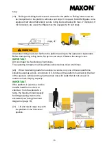


IMPORTANT


When using a handheld control with a spiral cable, the operator may initiate liftgate 

functions only while standing in the positions shown in the illustration. 


Operating position on the platform or vehicle floor 

The operator must stand a minimum of 10 inches from the front edge of the platform or 

rear edge of the vehicle floor. 


Operating position from the ground 

When operating the platform from the ground, the operator must stand at least 39 1/3 

inches from all edges of the platform and from the crushing edge between the platform 

and vehicle. 


Summary of Contents for GPC X1-LD

Page 1: ...GPC X1 LD liftgate GPC X1 LDF liftgate User Manual LIFT CORP 11921 Slauson Avenue Santa Fe Springs CA 90670 2221 P 800 227 4116 562 464 0099 F 888 771 7713 Date 08 2020 Part No 20 912 419...

Page 2: ...information MAXON LIFT CORP Corporate Office 11921 Slauson Avenue Santa Fe Springs CA 90670 2221 P 800 227 4116 562 464 0099 F 888 771 7713 Customer Service Parts USA Canada Mexico P 800 227 4116 F 88...

Page 3: ...r operator 9 2 8 Commissioning 10 2 9 Handling and behavior during operation 13 2 10 Danger notice sticker Safe handling of the liftgate 16 2 11 Permissible loads 17 2 12 Load diagram 18 Operation of...

Page 4: ...switched off 35 5 6 Emergency Platform moved by mechanical means 36 5 7 Malfunction 36 Decommissioning disassembly and disposal 37 Electrical circuit diagram 40 Hydraulic circuit diagram 41 Warranty l...

Page 5: ...liftgate Do not deviate from the instructions contained in this manual By doing so you risk injury damage to property and voiding of the warranty Make sure that this manual always remains with the li...

Page 6: ...flipped open 1 Platform 2 Warning flags 3 License plate light 4 License plate holder 5 Lifting cylinder 6 Support arm 7 Step 8 Lifting arm 9 Closing arm 10 Compact power unit 11 Closing cylinder 12 A...

Page 7: ...ridge plate 1 Platform 2 Warning flags 3 License plate light 4 License plate holder 5 Lifting cylinder 6 Lifting arm 7 Closing arm 8 Foot control 9 Compact power unit 10 Closing cylinder 11 Axle assem...

Page 8: ...cally locked out electrically Hydraulics The liftgate is driven by a compact power pack mounted on the supporting structure directly on the closing cylinder It serves to move the lifting or closing cy...

Page 9: ...ber and the rating plate The liftgate serial number is the liftgate s most important ID number It is required for all technical support spare parts orders and warranty claims and is found on every dev...

Page 10: ...minor or moderate injury NOTICE Failure to heed this notice can result in damage to property or the environment And IMPORTANT Important information or useful tip for correct use 2 2 Safety The Safety...

Page 11: ...hoses Danger from pressurized liquids and gases Hydraulic components lines can burst and cause injury Inspect hydraulic components lines at regular intervals maintenance schedule Install only state of...

Page 12: ...valve may be adjusted only by a qualified specialist using a test weight and a manometer Fuses Defective fuses may only be replaced by fuses that correspond to the values specified in the circuit dia...

Page 13: ...spection report dealing with the static and dynamic inspection performed before commissioning the liftgate is kept in the inspection record book The liftgate must be operated in accordance with the us...

Page 14: ...ts on the liftgate Watch out for potential crushing points Define and observe the danger zone including for third parties 6 Check that supports are correct positioned on a suitable surface before comm...

Page 15: ...purpose 10 Liftgates operated in areas of vehicle traffic or where the liftgate extends into these areas must be suitably protected against danger from vehicles 11 During operation the liftgate platfo...

Page 16: ...ing notice stickers on the vehicle or the absence of a load diagram missing rating plate may make it more difficult to recognize hazards and result in injuries Regularly check the condition of warning...

Page 17: ...lowered including platform tip 4 Do not unnecessarily stand within the liftgate s range of movement 5 Do not stand under the lifting device and load 6 Do not stand on the lifting device except for ope...

Page 18: ...a safe distance during operation when using the handheld control on page 22 13 Do not deliberately cause the lifting device to vibrate 14 Do not throw objects onto or from the lifting device 15 Place...

Page 19: ...IMPORTANT Dirt can impair the functioning of cart stops The operating company must keep these safety devices clean at all times 20 When transferring loads from vehicle to vehicle only one of the two p...

Page 20: ...dicate potential incorrect and correct usage of the liftgate This sticker is supplied with all new liftgates The installing company must place it in a clearly visible location on the inside of the veh...

Page 21: ...built in protection against loads that exceed the rated capacity or that are not within the correct loading distance and are moved from the vehicle to the platform Overloading of this type can for exa...

Page 22: ...When the platform is completely lowered it may be traversed loaded only with loads that do not exceed its rated capacity Operate the lifting and lowering functions only with the platform in the horizo...

Page 23: ...operate 3 2 Operation using the control panel membrane switch From the control panel all functions are initiated by pressing two different pushbuttons simultaneously The diagram shows which buttons a...

Page 24: ...be operated one after the other WARNING Be careful not to confuse the control elements for tilt up tilt down and lift lower Incorrect operation could injure third parties Define and observe the danger...

Page 25: ...onfuse the control elements for tilt up tilt down and lift lower Incorrect operation could injure third parties Define and observe the danger zone including for third parties WARNING Crushing or shear...

Page 26: ...unctions only while standing in the positions shown in the illustration Operating position on the platform or vehicle floor The operator must stand a minimum of 10 inches from the front edge of the pl...

Page 27: ...During loading and unloading of the platform the GPC X1 LD bridge plate and both of the GPC X1 LDF bridge plates must be folded open position with the platform completely lowered After use the bridge...

Page 28: ...side of the liftgate platform manually 6 Open the left vehicle door 5 Lower the liftgate platform using the control panel Lower or if you re standing on the platform using the foot controls or the opt...

Page 29: ...rols or the optional 3 button handheld control Tilt up Tilt down Lower Loading and unloading the liftgate 10 The liftgate platform is now ready for loading and unloading Loading the vehicle 11 Tilt up...

Page 30: ...Lower or if you re standing on the platform using the foot controls or the optional handheld control Lower so that you can close the left vehicle door 16 Close the left vehicle door 17 Fold up the rig...

Page 31: ...r tilt up tilt down or lift lower Incorrect operation could injure third parties Define and observe the danger zone including for third parties 20 Close the right vehicle door 19 Close the liftgate pl...

Page 32: ...nections are tight Check that cables and hoses are able to move freely Correct shearing and chafing points on cables and hoses Immediately replace damaged hydraulic hoses with new hoses of the same qu...

Page 33: ...gloves when handling hydraulic fluid Handle and dispose of hydraulic fluid in accordance with local regulations IMPORTANT Repairs to load bearing components are to be carried out only by an authorized...

Page 34: ...nexpected movement that results in injury WARNING Replace electrical system components only with approved original electrical components with EMC approval External influences on electrical equipment m...

Page 35: ...e drops to 12 volts the current doubles to 300 amperes WARNING This high current accompanied by a low voltage causes the copper winding to overheat As a result the protective coating on the copper win...

Page 36: ...ftgate activated LED on Power supply is functioning correctly Platform position 0 to approx 60 LED off Tilt sensor S1 in switching position is functioning correctly Corner lights are activated Platfor...

Page 37: ...panel control cabinet to power pack is defective Control lines in power pack are defective Control panel control cabinet is defective 3 Liftgate does not open or opens slowly Platform sticks at the ve...

Page 38: ...weight Load is not within the loading distance Load is too heavy Safety valve is incorrectly set Pump is defective Voltage is too low 10 Platform does not tilt up from ground when unloaded Control pa...

Page 39: ...attery main switch to stop the motor from running Then take the liftgate to the nearest authorized repair shop or call our customer service so that the defect can be corrected WARNING Electrical hazar...

Page 40: ...NT If the liftgate breaks down in this way contact customer service or an authorized repair shop for more information DANGER Danger Serious risk of death or injury When the liftgate is unsecured and t...

Page 41: ...e opened only with the aid of a crane or forklift When disposing of the liftgate the hydraulic system lifting and closing cylinders reservoir hydraulic pump solenoid valves cables high pressure hoses...

Page 42: ...nsioned springs Use only trained and qualified maintenance personnel WARNING Risk of injury during disassembly assembly particularly of safety devices e g removing solenoid valves due to improper or i...

Page 43: ...er disposing of packing materials store all parts in a secured manner and carefully remove transport locks WARNING When transport locks are removed parts may fall If parts fall fluid can escape Carefu...

Page 44: ...Electrical circuit diagram 40 Electrical circuit diagram...

Page 45: ...Hydraulic circuit diagram 41 Hydraulic circuit diagram...

Page 46: ...MAXON Part Number s 6 MAXON R M A and or Authorization if applicable see below 7 Person contacted at MAXON if applicable 9 2 Purchase Part Warranty Term of Warranty 1 Year from Date of Purchase Type...

Page 47: ...diagnosis of problem Warranty and Technical Information is available by calling Maxon s Customer Service Department NOTE Check with Customer Service Department for updated versions of Manuals on an a...

Page 48: ...Notes 44 Notes...

Page 49: ...45...

Page 50: ...46...

Reviews: