

General
4
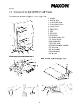
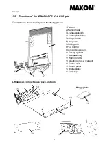
1.6 Description of the MAXON liftgate components
Electrical system/operating unit
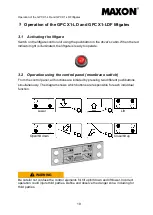
The individual functions are controlled via a very flat control panel with four membrane
switches (see page 19). The interface between the liftgate and the vehicle complies with
ETMA guidelines.
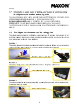
Foot controls
The foot controls on the platform are mounted inside a protective, die-cast aluminum
housing. They can be used to lower the liftgate to the ground and lift it to the height of the
vehicle floor. The platform automatically tilts up and down to a position horizontal with the
ground.
Priority control
The foot controls are a priority control. When the liftgate is operated via the foot controls,
other control options (control panel, handheld control) are automatically locked out
electrically.
Hydraulics
The liftgate is driven by a compact power pack mounted on the supporting structure
(directly on the closing cylinder). It serves to move the lifting or closing cylinder to the
desired position. The hydraulic cylinder’s connecting rods are nitrided.
Lifting gear
The lifting gear (flange brackets as well as lifting and closing arms) comes with its final
surface ex works and is painted black (RAL 9005). All bearing points are maintenance-
free and require no lubrication. The flange brackets and installation adapters are adapted
to the frame of the vehicle type ex works. The interface complies with the ETMA
standard. Each liftgate type is tested with 80,000 load changes before being approved for
production.
Platform
The platform comprises clipped-together aluminum hollow sections that are stabilized by
means of welded tip and end sections. The platform has a smooth back for optimally
accommodating advertising labels.
Summary of Contents for GPC X1-LD
Page 44: ...Electrical circuit diagram 40 Electrical circuit diagram...
Page 45: ...Hydraulic circuit diagram 41 Hydraulic circuit diagram...
Page 48: ...Notes 44 Notes...
Page 49: ...45...
Page 50: ...46...


