Fault diagnosis and fault elimination
32
Fault diagnosis and fault elimination
5.1 Explanation of diagnostic LED in the control unit
The control unit is the central control unit for the liftgate’s electrical system.
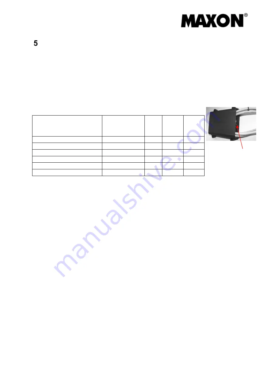
An LED (monitoring and diagnostic LED) integrated in the control unit serves as an
operating state and fault diagnosis indicator.
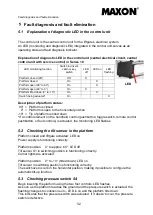
Explanation of diagnostic LED in the control unit (central electrical circuit, central
control unit with service control) in Series 10
Description of platform status:
90° = Platform is closed
0° = Platform is open to the horizontal position
-10° = Tip of platform is tilted down
*If a control element on the handheld control (pushbutton, toggle switch, remote control
pushbutton, or foot controls) is actuated, the monitoring LED flashes
5.2 Checking the tilt sensor in the platform
Platform closed and liftgate activated: LED on
Power supply is functioning correctly.
Platform position 0° to approx. 60°: LED off
Tilt sensor S1 in switching position is functioning correctly.
Corner lights are activated.
Platform position 0° to -10° (tilted down): LED on
Tilt sensor in switching position is functioning correctly.
The switchover occurs in the horizontal position, making it possible to configure the
automatic tilt-up function.
5.3 Checking pressure switch S4
Begin lowering the platform using the two foot controls: LED flashes.
As soon as the platform reaches the ground and the pressure switch is actuated, the
flashing changes to continuous on – LED is on and the platform tilts down.
This indicates that the pressure switch was actuated. If it doesn’t occur, the pressure
switch is defective.
LED monitoring function
Switch in driver’s
cabin or key
switch
LED
off
LED on
LED
flashing
Platform closed (90°)
Off
X
Platform closed
On
X
Platform open (90° to 60°)
On
X
Platform open (60° to 0°)
On
X
Platform tilted down (0° to -10°)
On
X
Switch being actuated*
On
X
LED
Summary of Contents for GPC X1-LD
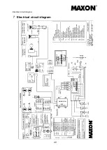
Page 44: ...Electrical circuit diagram 40 Electrical circuit diagram...
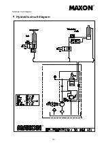
Page 45: ...Hydraulic circuit diagram 41 Hydraulic circuit diagram...
Page 48: ...Notes 44 Notes...
Page 49: ...45...
Page 50: ...46...

