


Installation
30
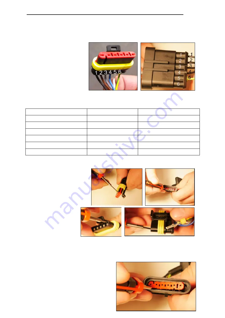
IMPORTANT:
A release tool is required for disassembling the SUPERSEAL
connector.
IMPORTANT:
When
reassembling, pay
attention to the position of
the individual wires! Return
the wires to their original
positions (see Fig. 39 for 1
and Fig. 38 for 2).
Legend:
Item 1
Socket housing
(Fig. 39) of the control unit
Item 2
Pin housing (Fig. 38) of the control panel
Using the release tool,
release the safety guard
from the socket housing
and pin housing (see
Fig. 40 and Fig. 41).
For the socket
housing, release
the latches on the
contact pins and
pull the wires out of
the back of the
housing (see
Fig. 42 and Fig. 43).
For the pin housing, first use the
release tool to pry out the safety
guard (see Fig. 44).
Control unit wires (1)
Pin No. and Wire No.
Control panel wires (2)
Black
1
Black
Brown
2
Black
Gray
3
Black
Blue
4
Black
White
5
Green/yellow
Green/yellow
6
Fig. 40
Fig. 39
Fig. 42
Fig. 44
Fig. 38
Fig. 41
Fig. 43
Summary of Contents for GPC X1-LDF
Page 1: ...GPC X1 LDF liftgate Installation Manual for Mercedes Benz Sprinter...
Page 11: ...Introduction 5 2 1 4 Accessories kit Fig 4...
Page 13: ...Introduction 7 2 1 5 Installation adapter kit 22 911 216 Fig 5...
Page 71: ...Useful information 65 8 2 Assembly drawings of installation adapters...
Page 72: ...Useful information 66 8 3 Electrical circuit diagram...
Page 73: ...Useful information 67 8 4 Hydraulic circuit diagram...


