Installation
35
No preparation according to ETMA Code A and Code B
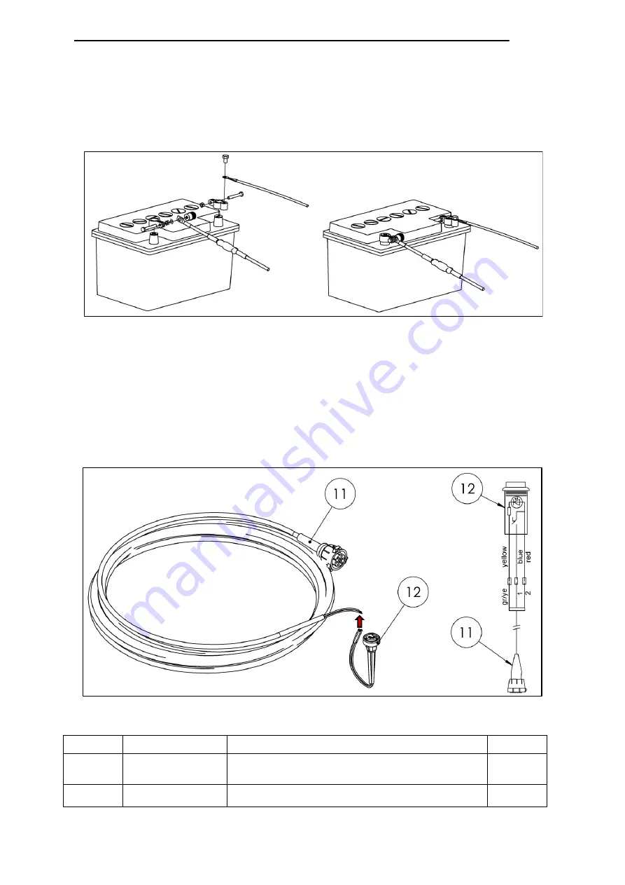
Power cable
R
oute the “power unit cable,” positive cable, and negative cable (25 mm²) for the
power supply to the terminals provided for the battery and connect (see example
in Fig. 52).
Cabin switch unit
Drill a 16 mm dia. hole for the cabin switch (12) in a suitable location on the
dashboard.
Snap the cabin switch (12) into the hole.
Route the cabin switch unit cable (11) from the lifting gear to the front.
Connect the cabin switch unit as shown in Fig. 53.
Excerpt from parts list: accessories kit
Item No. Part No.
Description
Qty.
11
20 906 975
Cabin switch unit cable 12 m with VEHH
connector
1
12
20 906 974
Cabin switch
1
Fig. 52
+
-
Fig. 53
Summary of Contents for GPC X1-LDF
Page 1: ...GPC X1 LDF liftgate Installation Manual for Mercedes Benz Sprinter...
Page 11: ...Introduction 5 2 1 4 Accessories kit Fig 4...
Page 13: ...Introduction 7 2 1 5 Installation adapter kit 22 911 216 Fig 5...
Page 71: ...Useful information 65 8 2 Assembly drawings of installation adapters...
Page 72: ...Useful information 66 8 3 Electrical circuit diagram...
Page 73: ...Useful information 67 8 4 Hydraulic circuit diagram...


