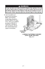
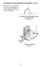
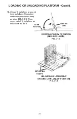
background image

29

6.

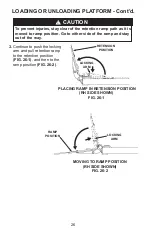
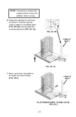
 Raise the platform to bed level 

    as follows. Hold the internal 
    control switch in the 

UP

 position 

(FIG. 29-1B) 

until the platform 

reaches bed level 

(FIG. 29-1A)

.

PLATFORM RAISED TO BED LEVEL

FIG. 29-2

FIG. 29-1A

NOTE:

 If necessary, release the 

control switch to stop the 
platform from moving.
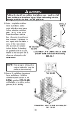
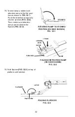
7.

 Move carts from the platform

    to inside the vehicle body 
    

(FIG. 29-2)

.

VEHICLE 

BODY

FIG. 29-1B

VEHICLE 

BODY

Summary of Contents for GPSLR Series

Page 1: ... MAXON Lift Corp 2020 M 08 13 REV G APRIL 2020 OPERATION MANUAL GPSLR 33 GPSLR 44 GPSTLR 33 GPSTLR 44 ...

Page 2: ......

Page 3: ...NTENTS SUMMARY OF CHANGES M 08 13 REVISION H 4 WARNINGS 6 LIFTGATE TERMINOLOGY 7 RECOMMENDED DAILY OPERATION CHECKS 8 DECALS 10 FORKLIFT ADVISORY 14 ROADSIDE OPERATION ADVISORY 15 LOADING OR UNLOADING PLATFORM 24 ...

Page 4: ... of this manual applies only to GPSLR lift gates with standard control switches All information about SmartStow control equipment was removed 7 Updated terminology to show standard external control switches 10 11 Changed Operation decal to latest decal with QR code and added decal with parts QR code 12 Added MAXGRIP decal for platforms with knurled surface 13 Decal H updated to show new retention ...

Page 5: ...5 THIS PAGE INTENTIONALLY LEFT BLANK ...

Page 6: ... all attached instruction decals and warning decals 11 Above all USE GOOD COMMON SENSE when operating the Liftgate 8 Do not move vehicle unless Liftgate is correctly stowed 6 Keep decals clean and legible If decals are illegible or missing have them replaced Get free replacement decals from Maxon 7 Never drive a forklift on the Liftgate platform 10 A correctly installed Liftgate will operate smoot...

Page 7: ...NTERNAL CONTROL SWITCH FRAME ASSY POWER PACK HYDRAULIC CYLINDER HYDRAULIC LOCK PLATFORM FLIPOVER DUAL RETENTION RAMPS TILT ARM LIFT ARM SLIDER ASSEMBLY INCLUDES MAIN BEAM PLATFORM BUFFERS SAFETY CHAIN EXTERNAL CONTROL SWITCHES ...

Page 8: ... tilt arms are clean no oil debris or corrosion NOTE Before you check the Liftgate park vehicle on flat ground and set the parking brake NOTE If any of the following operation checks reveal a need to service or repair Liftgate do not operate the Liftgate until a qualified mechanic services or repairs the Liftgate Visually check that pump cover is latched closed securely and undam aged Look for hyd...

Page 9: ...cle bed height Next lower the platform to ground level When the Liftgate is moving listen for unusual noises and look for a jerking motion or uneven movement on either side of the platform If service or repairs are not required or if completed stow the Lift gate With the platform un folded and raised to bed level check if the platform is level YES illustra tion If the platform looks like the YES i...

Page 10: ...AL E DECAL C SERIAL PLATE REF OPERATION DECAL P N 282681 01 CAUTION DECAL P N 283989 01 DECAL A FIG 10 1 CAUTION DECAL P N 282683 01 CAUTION DECAL P N 282682 01 DECAL P N 264507 DECAL P N 282721 01 PARTS QR CODE DECAL P N 299349 02 ...

Page 11: ...11 DECAL SHEET P N 282464 01 GPSLR 33 GPSTLR 33 P N 282464 02 GPSLR 44 GPSTLR 44 FIG 11 1 GPSLR 33 GPSTLR 33 ONLY GPSLR 44 GPSTLR 44 ONLY ...

Page 12: ...ECAL I DECAL J DECAL F DECAL B DECAL M DECAL M DECAL K DECAL A DECAL H DECAL G DECAL H DECAL L DECAL K DECAL K DECAL L DECAL L DECAL L DECALS Continued DECAL P N 264507 FIG 12 1 MAXGRIP DECAL P N 283293 01 ...

Page 13: ...13 DECAL SHEET P N 267432 01 FIG 13 1 ...

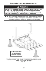
Page 14: ...14 FORKLIFT ADVISORY WARNING Keep forklift OFF of platform FIG 14 1 ...

Page 15: ...ffic can help reduce the chance of injury and damage WARNING ROADSIDE OPERATION ADVISORY NOTE MAXON recommends placing at least 2 traffic cones on the traffic side of the platform loading area as illustrated below Remove cones after platform is stowed and before moving the vehicle TRAFFIC CONES POSITIONED BY PLATFORM LOADING AREA GPSLR LIFTGATE SHOWN FIG 15 1 VEHICLE TRAFFIC APPROACHING FROM THIS ...

Page 16: ... platform from moving OPERATION UP DOWN TOGGLE SWITCH LOWEST POINT 6 ABOVE GROUND FIG 16 3 Damage will occur if Liftgate is not in correct position when operating the slide function Ensure platform arms have 6 of ground clearance at low est point before Liftgate is run out from under vehicle CAUTION CAUTION Ensure Liftgate is unchained before you deploy Liftgate for operation Possible injury and e...

Page 17: ...as shown in FIG 17 2 NOTE If necessary release the toggle switch to stop the platform from moving CAUTION Damage will occur if slide mechanism is not operated correctly Make sure Liftgate is fully extended latched before raising or lowering PLATFORM OUT LATCHED FIG 17 2 OUT SWITCH FIG 17 1 IN OUT TOGGLE SWITCH ...

Page 18: ...E GROUND FIG 18 1 5 Lower platform FIG 18 2 to ground level to load or unload on the ground Raise platform FIG 18 3 to vehicle bed level to load or unload vehicle Refer to section about LOADING OR UNLOADING PLATFORM in this manual PLATFORM LOWERED TO GROUND FIG 18 2 PLATFORM RAISED TO BED LEVEL FIG 18 3 OPERATION Continued ...

Page 19: ...up down toggle switch in the DOWN position FIG 19 1 until platform is on the ground FIG 19 2 WARNING 7 Ensure retention ramps are stowed See LOADING OR UNLOADING PLAT FORM Then fold the flip over FIG 19 3 Never operate control switch while folding the flipover WARNING PLATFORM LOWERED TO GROUND FIG 19 2 FOLDING FLIPOVER FIG 19 3 FLIPOVER NOTE If necessary release the toggle switch to stop the plat...

Page 20: ...E If necessary release the toggle switch to stop the platform from moving Damage will occur if Liftgate is not in correct position when operating the slide function Ensure platform arms have 6 of ground clearance at lowest point before Liftgate is run in under vehicle CAUTION OPERATION Continued UP SWITCH FIG 20 1 UP DOWN TOGGLE SWITCH LOWEST POINT 6 ABOVE GROUND FIG 20 2 6 GROUND ...

Page 21: ...21 9 Hold the external in out toggle switch in the IN position FIG 21 1 Slide the platform in to stow as shown in FIG 21 2 SLIDING PLATFORM IN TO STOW FIG 21 2 IN SWITCH FIG 21 1 IN OUT TOGGLE SWITCH ...

Page 22: ...owed securely against bottom of the vehicle body FIG 22 2 PLATFORM STOWED LATCHED FIG 22 2 Damage will occur if slide mechanism is not operated correctly Liftgate must be fully retracted latched and stowed before moving vehicle CAUTION OPERATION Continued UP SWITCH FIG 22 1 UP DOWN CONTROL SWITCH ...

Page 23: ... Liftgate is stowed and chained before you move vehicle Possible injury and equipment damage could result CHAIN SNAP HOOK CHAINING LIFTGATE FIG 23 1 TILT ARM 11 Chain Liftgate by hook ing snap hook to tilt arm FIG 23 1 ...

Page 24: ...n when cart is being raised or lowered on platform LOADING OR UNLOADING PLATFORM To prevent possible injury never operate control switch while unfolding the flipover or retention ramp WARNING UNFOLDING RETENSION RAMP RH SIDE SHOWN FIG 24 1 1 If equipped with a flipover and retention ramp unfold retention ramp FIG 24 1 by pushing down on locking arm Then pull strap UP and rotate ramp UP FIG 24 1 2 ...

Page 25: ...position FIG 25 1 Repeat for LH ramp FIG 25 2 RELEASING RETENTION RAMP TOP VIEW FIG 25 2 NOTE To unhook retention ramps stand at side of the flipover of the ramp that is to be unhooked After the retention ramps are unhooked the recommended place for handling the retention ramps is at the center of the free edges FIG 25 2 LOCKING ARM RAMP LH RAMP RH RAMP PULL HERE LOCKING ARM PULL HERE MOVING TO RE...

Page 26: ...t of the way 3 Continue to push the locking arm and pull retention ramp to the retention position FIG 26 1 and then to the ramp position FIG 26 2 MOVING TO RAMP POSITION RH SIDE SHOWN FIG 26 2 PLACING RAMP IN RETENSION POSITION RH SIDE SHOWN FIG 26 1 LOCKING ARM RAMP POSITION RETENSION POSITION LOCKING ARM LOADING OR UNLOADING PLATFORM Cont d ...

Page 27: ...s shown in FIG 27 1 If platform is equipped with cart dishes ensure the a set of wheels are seated in the dishes WARNINGS A load should never extend past the edges of the platform Do not place unstable loads on platform and do not allow load to exceed the lifting capacity of the Liftgate If standing on platform do not allow your feet to extend beyond the inboard edge of the platform RETENTION RAMP...

Page 28: ...AMPS LOADING OR UNLOADING PLATFORM Cont d ROTATING TO RETENTION POSITION RH SIDE SHOWN FIG 28 1 5 When carts are on the platform place the retention ramps in the retention position FIG 28 1 Then stand in the footprint area shown in FIG 28 2 ...

Page 29: ...osition FIG 29 1B until the platform reaches bed level FIG 29 1A PLATFORM RAISED TO BED LEVEL FIG 29 2 FIG 29 1A NOTE If necessary release the control switch to stop the platform from moving 7 Move carts from the platform to inside the vehicle body FIG 29 2 VEHICLE BODY FIG 29 1B VEHICLE BODY ...

Page 30: ...omply with WARNING LOADING PLATFORM AT BED LEVEL RAMP IN RETENTION POSITION FIG 30 1 Pulling the load from vehicle to platform can result in a fall from platform and serious injury When unloading vehicle always push the load out on the platform WARNING RETENTION RAMPS VEHICLE BODY 9 Lower the platform to ground level as follows Hold the internal control switch in the DOWN position FIG 30 2B until ...

Page 31: ...RAMP POSITION RH SIDE SHOWN FIG 31 1 10 Unload the platform at ground level as follows Reposition retention ramps to the ramp position FIG 31 1 Then move cart off the platform as shown in FIG 31 2 RETENTION RAMPS LOADING OR UNLOADING PLATFORM Cont d LOCKING ARM RAMP POSITION ...

Page 32: ...hes FIG 32 2 Then make sure retention ramps are hooked to the flipover FIG 32 2 ROTATING RAMP TO STOWED POSITION RH SIDE SHOWN FIG 32 1 STOWED FOLDING RETENTION RAMP RH SIDE SHOWN FIG 32 2 1 PUSH LOCKING ARM RAMP CATCH 11 Fold flipover FIG 32 3 on top of platform until latched FOLDING FLIPOVER FIG 32 3 FLIPOVER PLATFORM LATCH FLIPOVER ...

Page 33: ......

Reviews: