
20
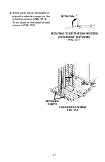
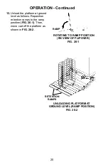
UNLOADING PLATFORM AT
GROUND LEVEL (RAMP POSITION)
FIG. 20-2
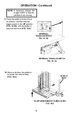
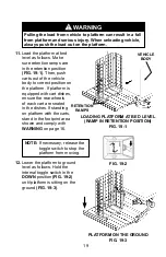
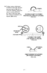
OPERATION - Continued
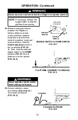
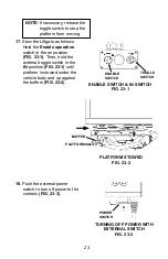
ROTATING TO RAMP POSITION
(RH VIEW OF FLIPOVER)
FIG. 20-1
RAMP
13.
Unload the platform at ground
level as follows. Reposition
retention ramps to the ramp
position
(FIG. 20-1)
. Then,
move cart off the platform as
shown in
FIG. 20-2
.
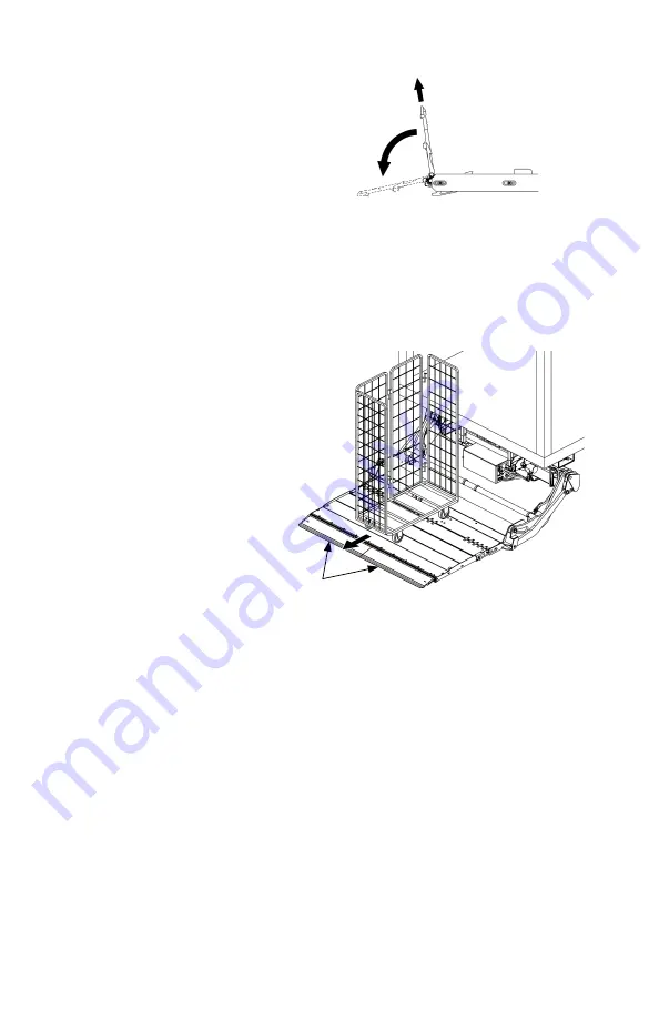
RETENTION
RAMPS
Summary of Contents for GPSLR
Page 1: ...M 08 13 DECEMBER 2008 OPERATION MANUAL MAXON Lift Corp 2008...
Page 2: ......
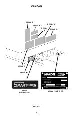
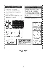
Page 9: ...9 DECAL SHEET FIG 9 1...
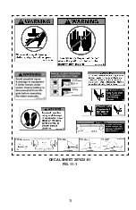
Page 11: ...11 DECAL SHEET 267432 01 FIG 11 1...
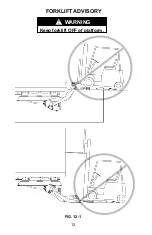
Page 12: ...12 FORKLIFT ADVISORY WARNING Keep forklift OFF of platform FIG 12 1...
Page 24: ......


