background image


Figure 1-6 


Figure 1-7 

2)  Place your hands either side of the system, press the front cover release buttons, and pull the 

front cover away from the main system (Figure 1-7). 

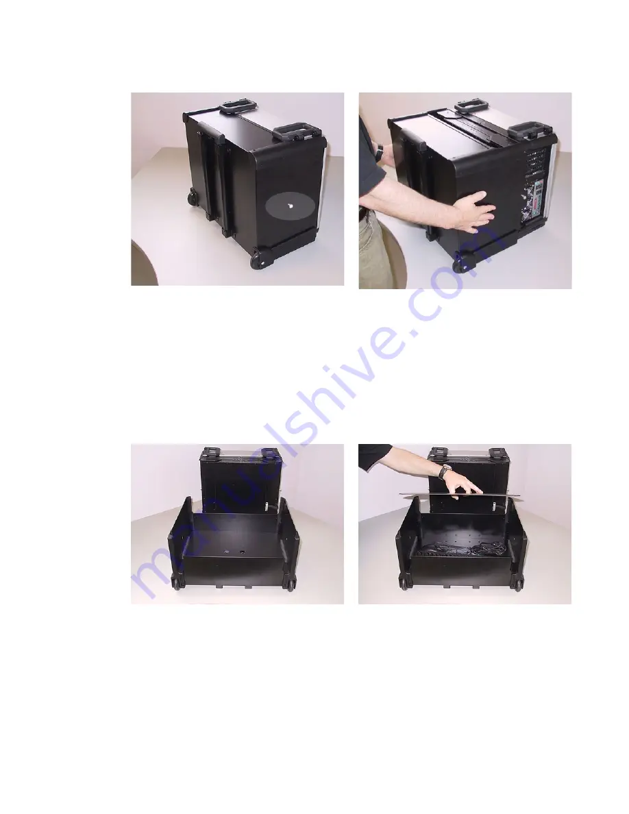
3)  Pull the front cover clear of the system and place it face down on the desktop (Figure 1-8).  

4)  Insert your thumb and index finger into the two holes located toward the center of the inside cover 

and gently pull this inside cover up and away to reveal the keyboard, mouse, power cable, and 
DVI-to-VGA connector (Figure 1-9). 

Note:

 The DVI-to-VGA connector may be required when adding an external display device as 

discussed later in this manual). 


Figure 1-8 


Figure 1-9 

5)  Remove the keyboard, mouse, and power cable from the front cover and place them on the table 

in front to the system. Set the front cover and its associated inside cover in a safe place. Place 
one hand underneath the system and the other hand on top of the system (Figure 1-10). Press 
down lightly with the hand on top of the system while gently pulling the bottom of the system 
forward with your other hand (Figure 1-11). 

Summary of Contents for X-Class

Page 1: ... sides of the unit and exhaust air from the vents at the front of the unit Power Requirements MaxPac X Class power supplies are auto sensing 100 to 240 VAC 50 to 60Hz units Ensure that the supplied power is sufficient stable and without spikes or surges for operation of your MaxPac and other required equipment Accessing and Connecting the Keyboard Mouse etc 1 Stand the MaxPac system upright on the...

Page 2: ...he keyboard mouse power cable and DVI to VGA connector Figure 1 9 Note The DVI to VGA connector may be required when adding an external display device as discussed later in this manual Figure 1 8 Figure 1 9 5 Remove the keyboard mouse and power cable from the front cover and place them on the table in front to the system Set the front cover and its associated inside cover in a safe place Place one...

Page 3: ...ext to the keyboard connector as shown in Figure 1 13 Alternatively you may remove the green USB to PS2 connector from the end of the mouse cable and then plug the mouse into one of the USB ports located just above the two PS2 ports Figure 1 12 Figure 1 13 8 Plug the power cord into the main power input port which is located on the left hand side of the system Figure 1 14 and then plug the other e...

Page 4: ...em Figure 1 15 11 While continuing to press down on the release catch pull the second screen away from the system Figure 1 16 Unfold this second screen completely as shown in Figure 1 17 Figure 1 16 Figure 1 17 Note You may hear a squeaking noise when you unfold the second screen This is caused by the polyurethane clutch and is part of the friction mechanism that holds the screen steady Do NOT app...

Page 5: ... 1 19 Figure 1 18 Figure 1 19 Figure 1 20 Figure 1 21 14 Now pull the left hand edge of the second screen away from the system Figure 1 20 Continue to pull this screen until it is completely unfolded Figure 1 21 Note You may hear a squeaking noise when you unfold the second and third screens This is caused by the polyurethane clutches and is part of the friction mechanism that holds the screens st...

Reviews: