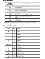
PV
SV
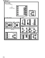
Repeat same steps
as above to display the
parameters listed at right.
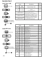
Operating display
Level1 (User level)
press the key
for 4 seconds to level 2
SET
Level2 (PID level)
Press the key
27.5
27.5
PV
SV
Operating display
Name
Description
Ex-
factory
OUTL
Output
percentage
Range of setting:0~100%
Skip
AT
Auto tuning
“RUN/NO”
to be used when setting PID
NO
AL1/RAMP/RATE
AL2/RAMP/RATE
AL3/RAMP/RATE
Alarm setting range: 0-100%F.S.
But if select ramp function, it will display ”rAmP”
setting range from 00.00 to 99.99
℃
/min If
select soak function, it will display “AL1” setting
range from 00.00 to 99.99 min/sec or hour/min.
If select slaver function, it will display “rAtE”
setting range from 0 to 9999. If select program
segment ending alarm function, it will display
“AL1”, setting range from 1-8 or 1-16
(AL2 and AL3 are the same as above)
0
Name
Description
Ex-
factory
P1
Main Control
Proportional Band
Range of setting:0-100%
ON/OFF at P=0
30
I1
Main Control
Integral Time
Range of setting:0-3600 Sec
Integral off at I=0
240
D1
Main Control
Derivative Time
Range of setting:0-3600 Sec
Derivative off at D=0
60
DB1
Main Control
Dead-band
Dead-band of main control
Range of setting:-10-+10
0
ATVL
Main Control
Auto tuning off-set
Range of setting:0-100% F.S.
0
CYT1
Main Control
Output cycle time
When output is SSR, it is set at 3, 4-20 mA is set at 1 but output
is relay usually it is set at 20. Range of setting:0-100 Sec
20
HYS1
Main Control
Hystersis
For ON/OFF control only
Range of setting :0.4-100
0.4
P2
Sub Control
Proportional Band
Range of setting:0-100%
ON/OFF at P=0
30
I2
Sub Control
Integral Time
Range of setting:0-3600 Sec
Integral off at I=0
240
D2
Sub Control
Derivative Time
Range of setting:0-3600 Sec
Derivative off at D=0
60
CYT2
Sub Control
Output cycle time
When output is SSR, it is set at 3, 4-20 mA is set at 1 but output
is relay usually it is set at 20. Range of setting:0-100 Sec
20
HYS2
Sub Control
Hystersis
For ON/OFF control only
Range of setting :0.4-100
0.4
RST1
Reset1
Adjust offset of output1 when I1 set at “0”
0
RST2
Reset2
Adjust offset of output2 when I2 set at “0”
0
AR
Anti- Integral
Setting range from 0-100 to limit integral
100
LCK
Function Lock
LCK=0000, SV, level 1 & 2 open
LCK=0001, SV, open only
LCK=0010, SV, level 1 open
LCK=0011, lock all except LCK
LCK=0100, SV, level 1 & prog. open
LCK=0101, SV,level 1,2,3 open
LCK=1010, level 4 open only
0101
P1
30
PV
SV
SET
i1
240
Press the key
Repeat the same steps
as above to display the
parameters listed at right.
27.5
27.5
PV
SV
Out L
100.0
PV
SV
SET
At
no
PV
SV
Press the key
SET
Return to “
“
Return to “
“
Operation flow
Operation flow
:
:
P.3


