42 CHAPTER 12: ELECTRICAL SYSTEM
Battery Switches
•
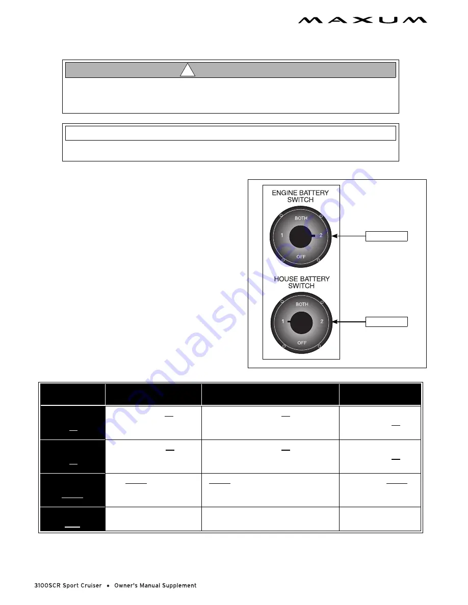
Each battery switch has four (4) positions.
•
The normal settings are:
Engine battery switch - position “2”.
House battery switch - position “1”.
•
Some "Standby Loads", such as the CO monitor, the auto-
matic bilge pumps, and the stereo memory, are not
affected by the battery switch since they are wired directly
to the battery (see the Wiring Diagrams in this Supplement
for more details).
•
If your boat is equipped with a bow thruster see the Bow
Thruster section of this Supplement for information about
the bow thruster battery switch.
Battery Switch
Position
Engine Starting
Accessories and Lights
Engine Alternator
POSITION
1
Battery 1
Provides Starting
Power
Battery 1
Provides Power for
Accessories and Lights
Charges
Battery 1
POSITION
2
Battery 2
Provides Starting
Power
Battery 2
Provides Power for
Accessories and Lights
Charges
Battery 2
POSITION
BOTH
BOTH Batteries
Provide Starting Power
BOTH Batteries Provide Power for
Accessories and Lights (not
advised unless engine is running)
Charges BOTH
Batteries
POSITION
OFF
Prevents Start/Run
Batteries Provide Power for
Standby Loads Only
Dot Not Run Engine
in this Position
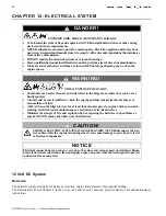
ENGINE & ELECTRICAL SYSTEM DAMAGE HAZARD!
NEVER change battery switch positions while the engine is running. It can cause damage to
your boat’s engine alternator.
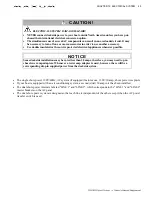
CAUTI ON!
!
Since the batteries on your boat were dealer-installed, the battery switch positions listed below
may vary. Make sure you get a full explanation of battery switch use from your selling dealer.
N OT I C E
NORMAL BATTERY
SWITCH POSITIONS
POSITION "2"
POSITION "2"
Summary of Contents for 3100 SCR
Page 1: ......
Page 2: ......
Page 65: ...CHAPTER 12 ELECTRICAL SYSTEM 59 AC Electrical System SHEET 3 OF 4...
Page 66: ...60 CHAPTER 12 ELECTRICAL SYSTEM Connector List SHEET 4 OF 4...
Page 67: ...Owner s Notes...
Page 68: ...Owner s Notes...
Page 69: ...Owner s Notes...
Page 70: ...Owner s Notes...
Page 71: ......
Page 72: ......


