1
FT200
(
48mm*48mm
)
FT204
(
48mm*96mm
)
FT205
(
96mm*48mm
)
FT207
(
72mm*72mm
)
FT209
(
96mm*96mm
)
7
2
72
67
.
2
67
.
2
68
.
4
7
48
68
.
4
7
44
.
6
44
.
6
48
9
6
91
.
2
48
44
.
6
68
.
4
7
9
6
91
.
2
9
1
.
2
96
68
.
4
7
FT200
1
2
7
17
18
10
16
15
14
OP1
OP2
INP2
RS
-
485
A
+
B
mA
V
TC
A
B
B
-
+
5V
AUX
-
AUX
+
AL1
AL2
85
~
265V
AC
L
N
13
12
11
9
8
6
5
4
3
FT207
B
B
mA
mA
V
V
TC
TC
A
A
B
B
FT204/FT209/FT205
TRS
OP1
OP2
RS
-
485
A
+
B
-
AL1
AL2
85
~
265V
AC
L
N
17
18
16
15
14
13
23
24
22
21
20
19
7
10
12
11
9
8
1
2
6
5
4
3
TRS
TRS
TRS
GND
-
GND
-
AUX
-
AUX
-
AUX
+
AUX
+
OP1
OP2
INP2
+
INP2
+
INP3
+
RS
-
485
A
+
B
-
AL1
AL2
AU3
AU3
85
~
265V
AC
L
N
11
12
10
17
18
16
15
14
13
7
9
8
1
2
6
5
4
3
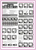
LCD display advanced digital temperature controller
User Manual
FT20X-800-C1
Please read this manual carefully and keep this manual for further reference
Features
0
Ambient temp 0-50 C, humidity 0-80%RH
Communication: RS-485, modbus-RTU, pattern 8-(N,O,E)-(1,2)
Special features: all parameters distributed in three levels, parameters can be manually
designate to different level
Add-on feature: auto/manual control, run/stop function, even SV input
Program version: PID mode, ramp up mode, temp constant mode, soft-start
Control mode: PID with auto-tuning, on/off, heating or cooling, cooling, 3 wires
proportional valve control, valve control with feedback signal, output restrain
Alarm:AL1/AL2 relay output, excitation, non-excitation, delay output, alarm lock function
Alarm mode: PV, deviation, absolute, band, alarm standby, PV deviation alarm ramp
start-up alarm, ramp end alarm, Loop break alarm,heater break alarm
Output: relay, SSR drive, analog, triac,re-transmission
0.2% measuring accuracy, maximum resolution 0.1 for TC and RTD input
LCD three color VA display, bar graphic,output percentage MV1/MV2 or feedback MVFb display
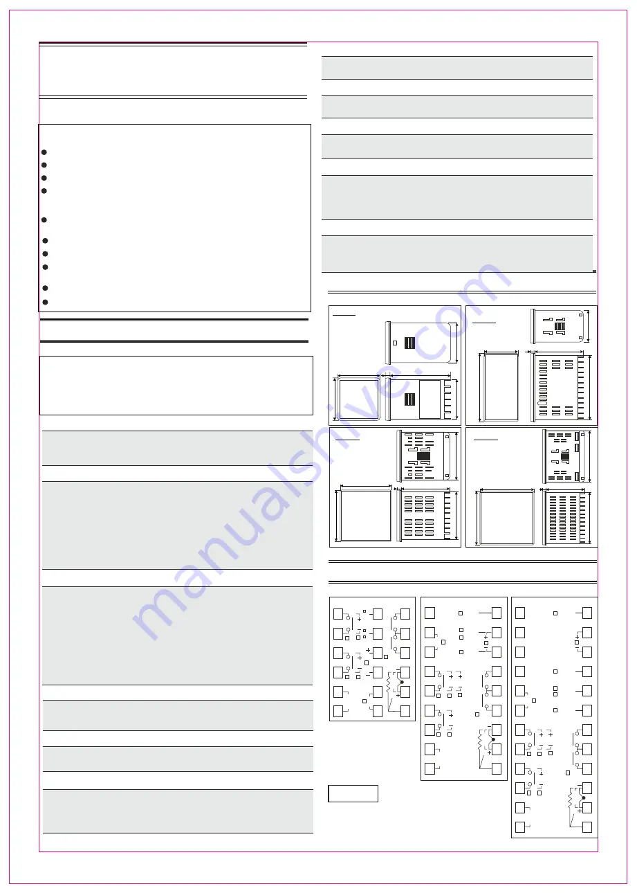
1: Model number and ordering information
Please check this ordering information and specify the code when order with us
Model
Item number( Panel size: width x height)
2. Size and mounting
FT200
FT204
FT205
FT207
Unit:mm
Unit:mm
Unit:mm
FT209
Unit:mm
3. Wiring diagram
Main output Relay
250Vac 5A(resistive load)
Alarm relay
250Vac 3A(resistive load)
4-20mA output(maximum load
resistance 500 ohm)
12VDC pulse output( 20mA)
Remark
Above is a general wiring diagram, please
always refer to the connection diagram on
the side of the controller
INP2/INP3 used for remote SV, or position
feedback or remote output% under manual
mode,Please refer to wiring diagram on the
unit for single phase or three phase triac output
option
:Controller type
1
U
R
Ramp and soak mode(with timer)
Standard PID type
R
V
D
4-20mA output
SSR Drive/Voltage pulse output
Relay output
E
0-10Vdc
F
0-20mA
:Power Source
5
96 85~265Vac 50/60HZ
:Number of Alarms
4
1
2
1 alarm
2 alarms
24 24Vac/24Vdc
:OUTPUT 1
2
5
0-5Vdc
7
1-5Vdc
T
Traic single phase zero-crossing trigger
A
Relay output, for motor valve direct act control
R
V
D
4-20mA output
SSR Drive/Voltage pulse output
Relay output
E
0-10Vdc
F
0-20mA
:OUTPUT 2
(output 2 is only available for cooling controller)
3
5
0-5Vdc
7
1-5Vdc
T
Traic single phase zero-crossing trigger
A
Relay output, for motor valve reverse act control
N
No output2( For single output controller, choose code N)
3
3 alarms
X
Motor valve direct/reverse control version(two relays)
:PV/SV re-transmission
6
N
No re-transmission function
A 4-20mA re-transmission via OP2
B 0-20mA re-transmission via OP2
E 0-10Vdc re-transmission via OP2
F 4-20mA re-transmission via AU3
G 0-20mA re-transmission via AU3
K 0-10Vdc re-transmission via AU3
:RS-485 Communication
7
N
No communication feature
K RS-485 modbus RTU communication
:AUX power source
8
N
No aux power
A 24Vdc isolated
B 24Vdc grounded
C 12Vdc isolated
D 12Vdc grounded
:Position feedback(analong feedback input from INP2)
9
N
No position feedback
C 0-5Vdc/potentiomter
A 4-20mA
D 1-5Vdc
B 0-20mA
E 0-10Vdc
:Remote SV setting
10
N
No remote SV feature
C 0-5Vdc via INP2
A 4-20mA via INP2
D 1-5Vdc via INP2
B 0-20mA via INP2
E 0-10Vdc via INP2
F 4-20mA via INP3
G 0-20mA via INP3
H 0-5Vdc via INP2
J 1-5Vdc via INP3
K 0-10Vdc via INP3
W D1/D2 terminals event input
:Manual output% remote setting
11
N
No remote SV feature
C 0-5Vdc via INP2
A 4-20mA via INP2
B 0-20mA via INP2
F 4-20mA via INP3
G 0-20mA via INP3
H 0-5Vdc via INP3
K 0-10Vdc via INP3
E 0-10Vdc via INP2
Vertical
Horizontal
FT20X
-
800
-
C1


