2
FT20X
-
800
-
C1
SET
SET
SET
SET
SET
SET
SET
SET
SET
A
/
M
A
/
M
A
/
M
A
/
M
A
/
M
A
/
M
A
/
M
A
/
M
A
/
M
SV1
AU2 AU3
MAN
MAN
MAN
MAN
MAN
MAN
MAN
MAN
MAN
COM
PRG
PRG
PRG
PRG
PRG
PRG
PRG
PRG
PRG
SV2 SV3 SV4
10
20
30
40
50
60
70
80
90
100
OP1 OP2
ATU
AU1
FT207
F1
F1
F1
F1
F1
F1
F1
F1
F1
F2
F2
F2
F2
F2
F2
F2
F2
F2
F3
F3
F3
F3
F3
F3
F3
F3
F3
SET
A
/
M
OP1
OP2
ATU
AU1
AU2
AU3
MAN
COM
PRG
SV1
SV2
SV3
SV4
10 20 30 40 50 60 70 80 90 100
F1
F2
F3
FT204
SET
A
/
M
SV1
AU2 AU3
MAN
COM
PRG
SV2 SV3 SV4
10
20
30
40
50
60
70
80
90
100
OP1 OP2
ATU
AU1
FT209
F1
F2
F3
SET
A
/
M
OP1 OP2
ATU AU1 AU2 AU3
MAN
COM
PRG
SV1
SV2
SV3
SV4
10 20 30 40 50 60 70 80 90 100
F1
F2
F3
PV
FT200
F1
F2
F3
SET
SV
OP1
OP2
ATU
AU1
AU2
MAN
COM
PRG
48mm
48mm
72mm
72mm
48mm
96mm
96mm
96mm
96mm
48mm
SET
A
/
M
MAN
PRG
F1
F2
F3
SET
SET
A
/
M
A
/
M
MAN
MAN
PRG
PRG
F1
F1
F2
F2
F3
F3
-
15
to
1300
0
to
1769
-
15
to
800
0
to
1800
-
15
to
1000
-
1999
to
9999
-
1999
to
9999
-
15
to
1300
0
to
2200
0
to
1600
-
15
to
400
-
199
to
800
0
to
2600 F
0
to
3216
F
0
to
1560
F
0
to
3276
F
0
to
1950
F
0
to
2600
F
0
to
3276
F
0
to
3000
F
0
to
782
F
-
326
to
1472
F
K
r
E
b
J
DC0
-
50mV
N
DC10
-
50mV
Wu3
_
Re25
S
t
Pt100
SET
A
/
M
MAN
MAN
PRG
PRG
F1
F2
F3
SET
A
/
M
MAN
PRG
F1
F2
F3
SET
SET
SET
A
/
M
A
/
M
A
/
M
MAN
MAN
MAN
PRG
PRG
PRG
F1
F1
F1
F2
F2
F2
F3
F3
F3
SET
SET
A
/
M
A
/
M
MAN
MAN
PRG
PRG
F1
F1
F2
F2
F3
F3
SET
A
/
M
MAN
PRG
F1
F2
F3
SET
SET
SET
SET
SET
SET
A
/
M
A
/
M
A
/
M
A
/
M
A
/
M
A
/
M
MAN
MAN
MAN
MAN
MAN
MAN
PRG
PRG
PRG
PRG
PRG
PRG
F1
F1
F1
F1
F1
F1
F2
F2
F2
F2
F2
F2
F3
F3
F3
F3
F3
F3
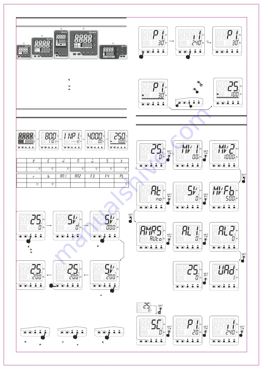
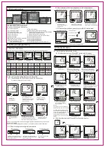
4. Panel description
FT205
PV window:display PV and parameter notation
SV window:display SV and parameter value
Bar graphic: indicate output%,feedback value
or re-transmission value
OP1: Indicate OP1 status
OP2: Indicate OP2 status
ATU: Indicate auto-tuning status
AU1: AL1 alarm status
AU2: AL2 alarm status
AU3: Reserved light
MAN: Manual control/soft-start indication
COM: Communication indication
PRG: Temp constant mode indication
Ramp and soak indication
SET: Main function key
A/M:Auto/manual switch key and enter key
:Shift key(F3 function key, such as ATU fast initiated
or go back to previous parameter)
:Numeric decrease(F2 function key)
:Numeric increase(F1 function key, Run/Stop)
SV1: Event input SV1 indication
SV2: Event input SV2 indication
SV3: Event input SV3 indication
SV4: Event input SV4 indication
SV1 and SV2 light together indicate remote-SV
5. Setting and programming
5.1 Power on initialization
Power on stage shows the software version and edition, input type and setting value range
au
to
m
a
tc
i d
is
p
la
y
au
to
m
a
tc
i d
is
p
la
y
au
to
m
a
tc
i d
is
p
la
y
au
to
m
a
tc
i d
is
p
la
y
Power on
all LED and indicators
light up
Software version
Software edition
Input sensor type
such as K thermocouple
SV setting value range
such as 0.0~400.0
Normal display status
Upper PV and lower SV
Notation
Sensor type
Range
Notation
Sensor type
Range
Reserved
Reserved
Reserved
Reserved
5.1 SV configuration and parameter configuration
5.2.1 How to change the SV setting value, use the short cut key.
0
For example: change the SV from 0 to 200 C
(1) PV/SV display mode
(2) SV configuration parameter
(3) SV configuration mode
Press once
or press once
or press once
Upper display shows SV
lower shows the current
SV value, with the unit’s digits
flashing the flashing digits
can be modifited
Press key, move the
cursor to the hundred’s
digits and flashing
(4) SV value modified
(5) Save the configuration
(6) PV/SV display mode
Press key, change the
hundred’s digit to “2"
Press SET save the configuration
or press A/M key save the changes
or controller will goes back to PV/SV
if you put the controller idle for 3 seconds
Configuration finish
back to PV/SV display
mode
Remark 1: SV setting parameter can be assigned to different parameter menus, referto S.F00
parameter for details
Remark 2: SV remote setting details, refer to “10. SV remote setting for more information”
5.2.2 How to configure all configurable parameters
SET
SET
SET
A
/
M
A
/
M
A
/
M
F1
F1
F1
F2
F2
F2
F3
F3
F3
Numeric increase
Numeric decrease
Shift the flashing digits
Press key to increase the numeric
of a parameter, press and hold can
fast increase the value
Press key to decrease the numeric
of a parameter, press and hold can
fast increase the value
Press key to shift the
flashing digit
5.2.3 Shift between parameters and go back to previous parameter
Save and exit to PV/SV display mode
(1) P1 parameter interface
(2)i1 parameter interface
(3)P1 parameter interface
SET
SET
A
/
M
A
/
M
MAN
PRG
F1
F1
F2
F2
F3
F3
SET
A
/
M
MAN
PRG
F1
F2
F3
SET
SET
SET
SET
A
/
M
A
/
M
A
/
M
A
/
M
MAN
MAN
MAN
PRG
PRG
PRG
F1
F1
F1
F2
F2
F2
F3
F3
F3
Shift to
Goes
back
Press SET key once
at any parameter to go to
next parameter
Press F3 key and hold to go
back to previous parameter
Go back to previous parameter
in this case, P1 to i1 and back to P1
5.2.4 Save configuration and go back to normal PV/SV display mode
(1) P1 parameter interface
Three approaches
1. Press SET for 3 seconds
2. Press A/M key once
3. Press SET and F3 together for once
6. Parameter menu
6.1 Factory default parameter menu
6.1.1 Quick start menu level 1(Press SET once to enter this menu)
PV/SV mode
Press SET once
Mornitoring parameter MV1
Mornitoring parameter MV2
Output1% value display parameter
MONI under menu PASS-0303 is
used for defining the status of MV1,
whether present this or hide this
Position feedback variable display
MONI under menu PASS-0303 is used for
defining the status of MVFb, whether
present this or hide this
Setting value paramter
(Under F00 menu grop)
Auto-tuning switch(F02 group)
No auto-tuning off
Yes auto-tuning on
AM.RS Control mode(F02 group)
Auto auto control mode
Man manual control mode
Stop stop mode
Alarm 1 value(F02 group)
Alarm 2 value(F02 group)
Communication address code
PV/SV display mode
Remark
PASS-0303 menu is an engineer menu
password is 0303, refer to 6.4 for details
F01-F08 is parameter group, some of
parameters were assigned to F01-F08
group, by configuring parameter S.F01-
S.F08, you can assign different
parameters to be presented in quick
start menu or not, refer to 6.2 for more
details
6.1.2 Quick start menu level 2(Press SET for 3 seconds to enter)
PV/SV mode
Press SET for 3 seconds
Input offset
(F04 group)
P1: Proportional band of output1
(F04 group)
i1:Integral time of output1(F04 group)
Output2% value display parameter
MONI under menu PASS-0303 is
used for defining the status of MV2,
whether present this or hide this


