SET
SET
A
/
M
A
/
M
MAN
MAN
PRG
PRG
F1
F1
F2
F2
F3
F3
SET
A
/
M
MAN
PRG
F1
F2
F3
SET
SET
SET
A
/
M
A
/
M
A
/
M
MAN
MAN
MAN
PRG
PRG
PRG
F1
F1
F1
F2
F2
F2
F3
F3
F3
SET
SET
SET
SET
SET
A
/
M
A
/
M
A
/
M
A
/
M
A
/
M
MAN
MAN
MAN
MAN
MAN
PRG
PRG
PRG
PRG
PRG
F1
F1
F1
F1
F1
F1
F2
F2
F2
F2
F2
F1
F1
F1
F1
F2
F2
F2
F2
F2
F3
F3
F3
F3
F3
SET
SET
A
/
M
A
/
M
MAN
MAN
PRG
PRG
F1
F1
F2
F2
F3
F3
SET
SET
SET
SET
A
/
M
A
/
M
A
/
M
A/M
MAN
MAN
MAN
MAN
PRG
PRG
PRG
PRG
F1
F1
F1
F1
F2
F2
F2
F2
F3
F3
F3
F3
SET
SET
SET
SET
A
/
M
A
/
M
A
/
M
A
/
M
MAN
MAN
MAN
MAN
PRG
PRG
PRG
PRG
F1
F1
F1
F1
F2
F2
F2
F2
F3
F3
F3
F3
SET
SET
A/M
A/M
MAN
MAN
PRG
PRG
F1
F1
F2
F2
F3
F3
SET
A
/
M
MAN
PRG
F1
F2
F3
SET
A
/
M
MAN
PRG
F1
F2
F3
SET
SET
SET
SET
A
/
M
A
/
M
A
/
M
A
/
M
MAN
MAN
MAN
MAN
PRG
PRG
PRG
PRG
F1
F1
F1
F1
F2
F2
F2
F2
F3
F3
F3
F3
SET
A
/
M
MAN
PRG
F1
F2
F3
SET
SET
A
/
M
A
/
M
MAN
MAN
PRG
PRG
F1
F1
F2
F2
F3
F3
SV
1
0
20
210
30
0
20
0
0
0
.
0
100
.
0
100
.
0
100
.
0
2
2
2
0
0
3
4
0
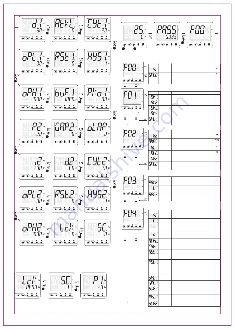
d1:Derivative time of output1
(F04 group)
ATVL: Auto-tuning offset
(F04 group)
CYTI: Control cycle time of
output1(FT04 group)
HYS1:Hysteresis for output 1
(FT04 group)
RST1: P1 reset wind-up
(FT04 group)
OPL1: Minimum output of output 1
(FT04 group)
OPH1: Maximum output of output 1
(FT04 group)
BUF1: Soft-start value for output 1
(FT04 group)
PKo1: Initial output value under
power-on manual control mode
(FT04 group)
oLAP: dual output heating and cooling
overlap area(FT04 group)
GAP2: Cooling side SV off-set
(FT04 group)
P2: Cooling ouptut proprotional
band(FT04 group)
i2: Cooling ouptut integral
time(FT04 group)
d2: Cooling ouptut derivative
time(FT04 group)
OPL2: Output 2 minimum output
(FT04 group)
RST2: Output 2 PID reset wind-up
(FT04 group)
HYS2: Output 2 ON/OFF
control hysteresis(FT04 group)
OPH2: Output 2 maximum output
(FT04 group)
LCK: Parameter access protection
quick start menu level 3 password
(F08 group)
Back to first parameter
Remark: All the parameters are distributed under ground F01,F02,F03,F04,F05,F06,F07,F08 some goes to
group F01 and others goes to F02 etc. S.F01-S.F08 parameter is used to define whether present or hide
specific parameters under different menu group
6.1.2 Quick start menu level 3(custom menu,access with password)
This is a customized menu, you can put those frequently used parameters which likely being incorrectly manipulated under
this menu, password is required if you want to access to this menu this will provent unauthorized access and configuration
LcK: password to access menu level 3
Customized parameters,there is no parameters under this menu as factory default
LcK: quick start menu(F08)
S.F08 parameter defines the
presence of this menu
when LcK=0808, press SET key
Remark: F01-F06, parameters were distributed to these groups
S.F01-S.F06 used to define the presence of these parameter groups
refer to “6.2 basic functional menu(F menu)” for more details
6.2 Basic functional parameter menu(F menu)
PV/SV display mode
Password interface
F00 menu interface
Press SET and F3 key once, goes to
password interface
Set PASS=0033 enter into F menu
F00 menu,press F1 or F2 key to
shift between F00-F08
F00 menu group
Notation
Name
Description
Default
setting value
define the
status of F00
group
parameters
Setting value
Range defined by(LSPL to USPL)
0: Do not present F00 under quick start menu
Press F1,F2,F3 to SV setting mode
1: Present F00 at quick start menu level 1
2: Present F00 at quick start menu level 2
3:Present F00 at quick start menu level 3
F01 menu group, for controller with event SV setting features only
Notation
Name
Description
Default
SV setting configured by external D1/D2
terminals SV1 D1: open D2:open, SV=SV1
SV setting configured by external D1/D2
terminals SV2 D1: open D2:close, SV=SV2
SV setting configured by external D1/D2
terminals SV3 D1: close D2:open, SV=SV3
SV setting configured by external D1/D2
terminals SV4 D1: close D2:close, SV=SV4
Event input SV1
Event input SV2
Event input SV3
Event input SV4
define the
status of F01
group
parameters
F02 menu group
Notation
Name
Description
Default
AT
Auto-tuning
CYT2: Cooling ouptut control
cycle time(FT04 group)
AM.RS
Operating mode
AL1
Alarm 1 value
AL2
Alarm 2 value
UAD
Device address
define the
status of F02
group
parameters
No.: Auto-tuning off
Yes:Auto-tuning on
Auto.: auto control mode
MAN:manual control mode
StoP: stop mode
Alarm value for alarm 1, range -1999~9999
Alarm value for alarm 2, range -1999~9999
Define device address in RS-485 system
F03 menu group, some of parameters under F03 might not be displayed due to
different controller version
Notation
Name
Description
Default
Ramp
Ramping up rate
Ramp rate under ramp up heating mode
0
Unit is C/minute
t1
timer range
t1 is a time duration for temperature constant mode or ramp up mode
minutes or seconds, t1=0, temperature constant mode disabled
parameter t1UN under PASS-0303 define the t1 unit
define the
status of F03
group
parameters
F04 menu group
Notation
Name
Description
Default
SC
Input offset
Input offset, to compenstate the error caused by sensor
Range, for temp: -199~199, for analog, -1999 to 1999
P1
P1 of output1
Proportional band of output 1, range 0-800
output 1 switch to ON/OFF control when P1=0, Hysteresis is HYS1
integral time
Derivative time
Integral time of output 1, range 0-3600 seconds
when i1=0, integral off
Derivative time of output 1, range 0-3600 seconds
When d1=0, derivative off
Auto-tuning
SV offset
Shift the SV value lower to prevent large
overshoot during auto-tuning process range -199-199
Cycle time
for output 1
cycle time for output 1, CYT1=20 seconds for relay
CYT1=2 seconds, CYT1 not applicable for analog output
Hysteresis
for output 1
When P1=0, ON/OFF control, HYS1 0.1-900
Heating: OP1 stop PV>SV
OP1 active when PV<SV-HYS1
Cooling: OP1 active when PV>SV+HYS1
OP1 stop PV<SV
Time
proportional
reset
When i1=0,d1=0, pure proportional control, rSt1 is reset value
Heating, out 1%= (SV+rst1-PV)/P1*100%
Cooling, out 1%=(PV-SV-rst1)/P1*100%
this used to suppress overshoot at start-up for PID control
Heating, suppress more when rst 1 gets smaller
Cooling, suppress more when rst 1 gets bigger
range: -199~199
minimum
output for out1
maximum
output for out1
Minimum output value
0.0 to 100.0%
Maximum output value
0.0 to 100.0%
Output 1
restrain
Output restrain for analog output, output restriction,
only applicable for analog output controller
for example, if buF=5%, means the output changing ratio
will be less than 5% per second
Initial
output %
Define the output ratio when temperature
configured as manual output after power on
heating/cooling
overlap
Heating/cooling control overlap.
range 0-100, overlap area is (SV-OLAP)~(SV+OLAP)
To the next page
0: Do not present in quick start menu
1: Present F00 at quick start menu level 1
2: Present F00 at quick start menu level 2
3:Present F00 at quick start menu level 3
0: Do not present in quick start menu
1: Present F00 at quick start menu level 1
2: Present F00 at quick start menu level 2
3:Present F00 at quick start menu level 3
0: Do not present in quick start menu
1: Present F00 at quick start menu level 1
2: Present F00 at quick start menu level 2
3:Present F00 at quick start menu level 3
FT20X
-
800
-
C1
3


