4
-
15
to
1300
0
to
1769
-
15
to
800
0
to
1800
-
15
to
1000
-
1999
to
9999
-
1999
to
9999
-
15
to
1300
0
to
2200
0
to
1600
-
15
to
400
-
199
to
800
0
to
2600
F
0
to
3216
F
0
to
1560
F
0
to
3276
F
0
to
1950
F
0
to
2600
F
0
to
3276
F
0
to
3000
F
0
to
782
F
-
326
to
1472
F
K
r
E
b
J
DC0
-
50mV
N
DC10
-
50mV
Wu3
_
Re25
S
t
Pt100
A
/
M
SET
SET
SET
A
/
M
A
/
M
A
/
M
MAN
MAN
MAN
PRG
PRG
PRG
F1
F1
F1
F2
F2
F2
F3
F3
F3
SET
SET
SET
SET
SET
A
/
M
A
/
M
A
/
M
A
/
M
A
/
M
MAN
MAN
MAN
MAN
MAN
PRG
PRG
PRG
PRG
PRG
F1
F1
F1
F1
F1
F2
F2
F2
F2
F2
F1
F1
F1
F1
F1
F2
F2
F2
F2
F2
F3
F3
F3
F3
F3
SET
0
80
0
0
0
0
2
180
2
10
20
210
30
20
0
0
0.0
100.0
2
0
0
2
0
dP
LSPL
USPL
0
400
0
F
:
:
5
0
to
60
-
1999
~
9999
-
1999
~
9999
-
1999
~
9999
-
1999
~
9999
00
to
16
00
to
16
UNIt
PVFt
IdNO
bAUd
UCR
0 or
1
0
,
1
,
2
0
-
255
2
.
4
4
.
8
9
.
6
19
.
2
N
,
O
,
E
11
10
0
0
1
9
.
6
N
0
-
200
0
,
1
,
2
0
Stnd
CYCL
PHAS
60
PHAS
0
to
9999
0
1
1
1
PENd
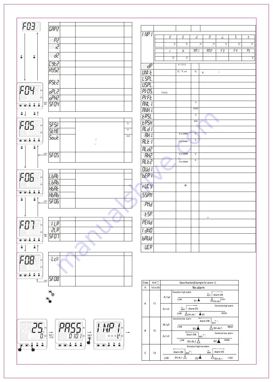
From the previous page
Notation
Name
Description
Default
Cooling control
SV offset
Define the cooling control SV value
cooling contorl SV=SV+GAP2, Range: 0~200
For example, SV=100, GAP2=10
Then cool side SV=100+10
P2 for
cooling control
Proportional band for output 2, unit is degree
range 0~800, P2=0 for ON/OFF control mode
Integral time
I 2 for output 2
Derivative time
for output 2
Derivative time for output 2
range 0~3600
d2=0 derivative action off
seconds
Integral time for output 2
range 0~3600 seconds
i2=0 integral action off
Control period
for output 2
Control period for output 2, 20 seconds for
relay output, 2 seconds for SSR drive output
Hystersis for
output 2
When P2=0, on/off control for out2.HYS2,range 0.1
~900, OP2 active when PV>SV+GAP2+HYS2
OP2 stop when PV<SV+GAP2
time
proportional
reset, rSt2
When i2=0, d2=0, proportional control
out2 %=(PV-SV-GAP2-rst2)/P2*100%
suppress the overshoot after power on
range: -199~199
Minimum
output for out 2
Maximum
ouptut for out 2
Minimum output for output 2
range 0.0~100%
Maximum output for output 2
range 0.0~100%
Define status
of F04 group
parameters
0: Absent
1:Present in quick start menu 1
2:Present in quick start menu 2
3:Present in quick start menu 3
F05 group parameters for controller with soft-start function only
Notation
Name
Description
Default
Soft-start SV
Soft-start
period
Soft-start
out%
SFSV range: -199~3275
StME range: 0~100 minutes
Sout range: 0.0~100.0%
Soft-start function
1. Power on, heating control, if PV< SFSV, soft start active
2. Power on, cooling control, if PV>SFSV, soft start active
3. MAN indicator flashes, out% = “Sout” value
4. PID heating, when PV SFSV or StME time reached,
soft-start off
5. PID cooling, when PV<SFSV or StME time reached,
soft-start off
6. MAN indicators off when soft-start terminated
7. StME=0, soft-start function disabled
Define status
of F05 group
parameters
0: Absent
1:Present in quick start menu 1
2:Present in quick start menu 2
3:Present in quick start menu 3
F06 group parameters for LBA(loop break alarm)and HBA(heater break alarm) only
Notation
Name
Description
Default
LBA check
time
LBA temperature
differential
Heater short
circuit time
Temperature
differential
Define status
of F06 group
parameters
0: Absent
1:Present in quick start menu 1
2:Present in quick start menu 2
3:Present in quick start menu 3
Under heating mode(100% output),if the temperature
did not increase LbAb within LbAt period, LBA will be
triggered
Under cooling mode(100% output), if the temperature
did not drop LbAb within LbAt period, LBA will be triggered
Under heating mode, if temperature increase HbAb
within HbAt period at output 0% HBA goes off
Under cooling mode, if temperature drops HbAb within
HbAt period at output 0% HBA goes off
F07 group parameters
Notation
Name
Description
Default
ALM1 interlock
ALM2 interlock
if alarm 1 interlocked, 1LR=1
put 1LR=0 can disengage the interlock
F08 group parameters
Notation
Name
Description
Default
Access
protection
and password
for quick start
menu 3
=0/1: all parameters can be modified
=2: F06 group of parameters locked
=3: F05,F06 parameters locked
=4: F04,F05,F06 parameters locked
=5:
F03,F04,F05,F06 parameters locked
=6: F02,F03,F04,F05,F06 parameters locked
=7: F01,F02,F03,F04,F05,F06 parameters locked
=8: F00,F01,F02,F03,F04,F05,F06 parameters locked
=0808: Press SET to quick start menu 3
Define status
of F08 group
parameters
0: Absent
1:Present in quick start menu 1
2:Present in quick start menu 2
3:Present in quick start menu 3
Three approaches to exist and save the configuration under F menu
1: Press SET key for 3 seconds
2: Quick press A/M key once
3:Press SET and F3 at the same time
6.2 Engineer paremeter (PASS-0101 menu)
PV/SV display mode
Password interface
Engineer parameter
Press SET and F3 at the same
time enter into PASS interface
SET PASS=0101
Press SET to F menu
Input sensor code selection
Depends on the specific functions
some of parameter may or may not be available
Notation
Name
Description
Default
Remark
Input sensor code selection INP1
Symbol
input
range
Symbol
input
range
Reserved
Reserved
Reserved
Reserved
Decimal point
Display unit
SV lower limit
SV higher limit
input offset
Input filter strength
lower limit display for
analog input
higher limit display for
analog input
Transmission output
lower limit tRSL
Transmission output
lower limit tRSH
TC/RTD input, 0: without decimal point, 1: 1 decimal point
Analog input: 0: without decimal point, 1: 1 decimal point, 2: 2 decimal points
3: 3 decimal points
Celcius
Fahrenheit
No:No unit
SV lower limit
Remote-SV lower limit input display value
SV higher limit
Remote-SV higher limit input display value
Temp: -199~3276
Analog: -1999~9999
Temp: -199~3276
Analog: -1999~9999
Temp: -199~199
Analog: -1999~9999
To compensate the input error
caused by the sensor
1-30 normal input filter strength
31-60 enhanced input filter strength
Display for analog input at its lower limit value “ANL1"
Display for analog input as its higher limit value “ANH1"
Display for re-transmission at its lower limit value
Display for re-transmission at its higher limit value
Alarm mode for alarm 1
Alarm hystersis
for alarm 1
Alarm 1 delay time
Alarm mode for alarm 2
Alarm hystersis
for alarm 2
Alarm 2 delay time
OP1 output mode
OP1 analog output
restriction
motor valve
travel time
Triac triggering mode
Program execution
mode
TSP
To configure the alarm mode of alarm 1
Hysteresis value for alarm 1
Alarm delay time for alarm 1 only applicable for ALd1=01~06
and 11~16,Alarm 1 will be triggered after delay time ALt1
To configure the alarm mode of alarm 2
Hysteresis value for alarm 2
Alarm delay time for alarm 2 only applicable for ALd2=01~06
and 11~16,Alarm 2 will be triggered after delay time ALt2
seconds
0: reverse control(heating) 1:direct control(cooling)
0: output restriction off
1: output restriction on
2: output restriction on when output increase,
restriction off when output decrease
This parameter assign the travel time for the motor valve
means the time for the valve from full open to full close
this is only application for motor valve without position feedback
Stnd: SSR Drive output, zero-crossing trigger
CYCL:Random trigger
PHAS:Phase angled trigger
Only applicable for temp constant and ramp and soak mode
0: Standard mode
1: temp constant mode
2: ramp and soak mode
This parameter defines the temperature
when the timer kicks in
Temperature(TSP) for timer kicks in= SV-tSP
when PV SV-tSP, and stay for 5 seconds then timer kicks in
=0, PID control off when timer finish
=1, PID control goes on when timer finish
power interruption or press F1 for 3 seconds will re-start
Device address configuration
2.4 Baud rate 2400 bps
4.8 Baud rate 4800 bps
9.6 Baud rate 9600 bps
19.2 Baud rate 19200 bps
N: 8 data bit, + No 1 stop bit(8N1)
O: 8 data bit, + odd 1 stop bit(8O1)
E: 8 data bit, + Even 1 stop bit(8E1)
Alarm mode(ALd_=00~16)
10: No alarm
11: Deviation high alarm
12: Deviation low alarm
13: Deviation high/low alarm
14: Deviation band alarm
15: Process high alarm
16: Process low alarm
00: No alarm
01: Deviation high alarm with standby function
02: Deviation low alarm with standby function
03: Deviation high/low alarm with standby function
04: Deviation band alarm with standby function
05: Process high alarm with standby function
06: Process low alarm with standby function
09: LBA alarm
19: HBA heater short circuit alarm
17: Timer kick-in alarm
18: Timer finish alarm
21: Setting value high alarm
22: Setting value low alarm
23: Process value limit value
6.2.1 Alarm mode details
>
if alarm 2 interlocked, 1LR=2
put 2LR=0 can disengage the interlock
Define status
of F07 group
parameters
0: no shortcut for interlock disengage
1: shortcut for interlock disengage available
Press F1 and F2 at the same to quick acess to 1LR and 2LR
seconds
FT20X
-
800
-
C1


