0
0
0
,
1
0
,
1
0
0
5
V
W
P
R
Q
3
4
21
22
23
09
19
17
18
SV
SV
Ah1
Ah1
SET
SET
SET
SET
SET
SET
A
/
M
A
/
M
A
/
M
A
/
M
A
/
M
A
/
M
MAN
MAN
MAN
MAN
MAN
MAN
PRG
PRG
PRG
PRG
PRG
PRG
F1
F1
F1
F1
F1
F1
F2
F2
F2
F2
F2
F2
F3
F3
F3
F3
F3
F3
1
0
0
0
SET
SET
SET
A
/
M
A
/
M
A
/
M
MAN
MAN
MAN
PRG
PRG
PRG
F1
F1
F1
F2
F2
F2
F3
F3
F3
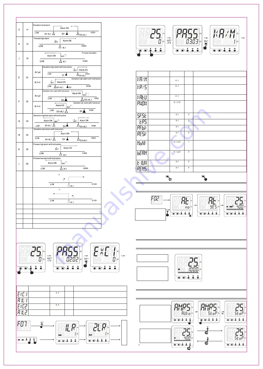
SV high alarm
When SV AL1, AL1 on, When SV<AL1-AH1, AL1 off
AL1 ON
AL1 OFF
SV low alarm
When SV AL1, AL1 on, When SV>AL1+AH1, AL1 off
Process value limit alarm
LBA loop break alarm
Heater short circuit alarm
timer kick-in alarm
timer finish alarm
Engineer parameter
Password interface
6.3 Engineer paremeter (PASS-0202 menu)
PV/SV display mode
Press SET and F3 at the same
time enter into PASS interface
SET PASS=0202
Press SET to F menu
6.4 Engineer paremeter menu 3 (PASS-0303 menu)
Engineer parameter
Password interface
PV/SV display mode
Press SET and F3 at the same
time enter into PASS interface
SET PASS=0303
Press SET to F menu
Auto/manual control
configuration
Depends on the specific functions
some of parameter may or may not be available
Notation
Name
Range
Factory
default
Remark
Auto/manual control
switch configuration
0: A/M key disabled
1: A/M Keky enable( press A/M key 3 seconds to switch)
Run/Stop function
configuration
0: Disable RUN function active by F1 key
Disable STOP function active by F2 key
1: Enable RUN function active by F1 key
Enable STOP function active by F2 key
0: Disable auto-tuning active by F3 key
1: Enable auto-tuning active by F3 key
Auto-tuning
short cut key
Power on
control mode
0: Auto control mode after power on
1: Stop mode after power on
2: Manual control mode after power on
intial output value defined by PK01 parameter
3: Controller continue the status from where it left off
soft-start function
configuration
0: Disable soft-start function
1: Enable soft-start function
0: PV re-transmission
1: SV re-transmission
0: Position feedback disabled
1: Position feedback enable for close loop control
Re-transmission
configuration
Position feedback
configuration
Remote SV
Quick start menu 1
configuraion
Bar graphic display
configuration
Timer unit
manual output % remote
setting
0: Remote SV off
1: Remote SV on( panel SV setting off)
2: Remote SV on(panel SV setting on)
0: MV1,MV2,MVFb absent in quick menu 1
1: MV1,MV2, present in quick menu 1, MVFb absent
2: MVFb present in quick menu 1, MV1,MV2 absent
3: MV1,MV2,MVFb present in quick menu 1
0: Bargraphic for OP1 %
1: Bargraphic for OP2 %
2: Bargraphic for TRS%
3: Bargraphic for MVFb%
0: Manual output % set via key pad
1: Manual output % set via remote signal
0: Timer unit “ second”
1: Timer unit “ minute”
A
/
M
SET
Three approaches to exist and save the configuration under F menu
1: Press SET key for 3 seconds
2: Quick press A/M key once
3:Press SET and F3 at the same time
7. Auto-Tuning
MAN
PRG
SET
SET
SET
SET
SET
A
/
M
A
/
M
A
/
M
MAN
MAN
MAN
PRG
PRG
PRG
F1
F1
F1
F2
F2
F2
F3
F3
F3
F3
2s
Enter into F02 menu
choose “AT”
F3 key quick access to AT
If PASS-0303 KAtU=1
thisparameter set as 1
enable the quick access to AT via
F3 key for 2 seconds
Change the AT value from NO to YES to active the auto-tuning, auto-tuning is an ON/OFF
control mode, AT light flashes, AT light off when auto-tuning finished, P.I.D values will
be caculated automatically.
Configure the ATVL parameter under F04 menu, the SV can be shifted down to prevent large overshoot during the auto-tuning
Auto-tuning will be terminated if you enter into manual mode or STOP mode or encounter a power interruption
Auto-tuning will be terminated if the AT value change from YES to NO during the auto-tuning process
Under remote SV pattern, the SV will be locked if auto-tuning actived, the auto-tuning SV will be the SV
when it was locked, recommend to switch to panel SV setting mode before auto-tuning
*Please start the auto-tuning at the ambinent temp to get best auto-tuing result
8. Auto manual control switch
SET
A
/
M
MAN
PRG
F1
F2
F3
Auto/manual switch via parameter
menu
Locate AMRS under F02 group
Set MAN as the AMRS value
Auto/manual switch via A/M key
on the front panel
If KA/M=1 under PASS-0303 menu
then shortcut key A/M on the front is
enabled you can switch between
auto/manual conotrol
on the front panel
Manual control mode
How to switch back to auto control mode from manual mode
1: Goes to F02 menu and locate AMRS, change the value from MAN to Auto. exit and save
2: Press A/M key for 2 seconds to auto control mode
1: Manual control mode, MAN light on
2: Lower display indicates the output %
3: Use F1 and F2 key to quick configure the output %
under remote setting mode, the output % will be
determined by external analog signals, MAN
indicator flashes( refer to PASS-030 REMS)
** Controller can be configured as manual control
mode right after power on,the output % defined
by parameter Pk01 and POWN parameters
9. RUN/STOP function
SET
SET
SET
SET
A
/
M
A
/
M
A
/
M
MAN
MAN
MAN
PRG
PRG
PRG
F1
F1
F1
F2
F2
F2
F3
F3
F3
SET
A
/
M
MAN
PRG
F1
F2
F3
SET
A
/
M
MAN
PRG
F1
F2
F2
F3
F1
RUN/STOP switch via parameter menu
Goes to F02 menu and locate AMRS
put StoP on the lower display and
set to STOP mode
put Auto on the lower display and
set to AUTO control mode
Swtich RUN/STOP via F1 on the panel
Goes to PASS-0303 menu, set KR/S
=1 to enable the shortcut key for
RUN/STOP changover
Press F1 for 2 seconds to switch
between RUN/STOP
STOP
ACTIVE
Output terminated, alarm off
under STOP mode
Auto mode
Stop mode
Engineer parameters menu “0202"(PASS-0202)
Notation
Name
Range
Default
Remark
AL1 relay
excitation
AL2 relay
excitation
AL2 interlock
AL1 interlock
0: AL1 relay pull-in when alarm 1 triggered
1: AL1 relay release when alarm 1 triggered
0: AL1 output standard mode
1: AL1 output interlock mode
0: AL2 relay pull-in when alarm 2 triggered
1: AL2 relay release when alarm 2 triggered
0: AL2 output standard mode
1: AL2 output interlock mode
AL1 relay excitation configuration
6.3.1 Alarm interlock disenaged procedure
Approach 1: go to F07 menu, press SET
Approach 2: when S.F07=1, press
F1 and F2 for 2 seconds
AL1 interlock, 1LR=1
AL2 interlock, 2LR=1
SET
SET
put 1LR=0 to unlock the
AL1 interlock
put 2LR=0 to unlock the
AL2 interlock
Press SET for
3 seconds
Press SET
P
V
/S
V m
on
it
or
in
g m
od
e
Note: The alarm action will be suppressed right after power on even the condition is satistifed, and the alarm standby on works 1 time
right after power on, the alarm will go off if the condition satisfied again after supression at the first time
FT20X
-
800
-
C1


