K
E
K
K
K
E
K
E
E
E
K
E
0
.
0
0
.
0
0
0
.
0
0
0
.
0
0
0
.
0
0
.
0
0
0
0
0
0
to
to
to
to
to
to
to
to
to
to
200
200
.
0
200
.
0
400
400
300
.
0
300
300
.
0
600
400
.
0
400
.
0
400
1300
800
A4
A6
B3
A2
D2
A4
D2
D4
A8
D3
Wu3
_
Re25
S
R
B
N
S
R
B
N
W
0
0
2 0 0
0
60 0
to
to
to
to
to
1600
1769
1800
1300
2200
B6
B8
B8
B3
B0
T
T
T
to
to
D4
A4
J
J
J
J
J
J
0
0
0
to
to
to
to
to
300
400
1000
A3
D3
D4
A4
A0
AN1
AN2
AN3
AN3
AN4
AN4
AN4
AN3
AN3
10
to 9999
-
1999
to
to
99
.
99
9
.
999
-
19
.
99
-
1
.
999
to 999
.
9
-
199
.
9
0
0
0
0
-
100
-
200
-
200
-
200
D
D
D
D
D
D
D
D
D
D
D
D
D
D1
D2
G2
F3
F2
A1
A2
A4
A8
C2
C4
C6
C8
100
200
400
800
200
400
600
800
**
6
B
mA
V
TC
A
B
OP1
OP2
RS
-
485
A
+
B
-
AL1
AL2
85
~
265V
AC
L
N
17
18
16
15
14
13
23
24
22
21
20
19
7
10
12
11
9
8
1
2
6
5
4
3
TRS
GND
-
+
5V
INP2
+
INP3
+
AU3
SET
SET
SET
A
/
M
A
/
M
A
/
M
MAN
MAN
MAN
PRG
PRG
PRG
F1
F1
F1
F2
F2
F2
F3
F3
F3
SET
A
/
M
MAN
PRG
F1
F2
F3
SET
A
/
M
MAN
PRG
F1
F2
F3
SET
A
/
M
MAN
PRG
F1
F2
F3
SET
SET
A
/
M
A
/
M
MAN
MAN
MAN
MAN
MAN
MAN
MAN
PRG
PRG
PRG
PRG
PRG
PRG
PRG
F1
F1
F2
F2
F2
F3
F3
F3
D1
D2
220V
M
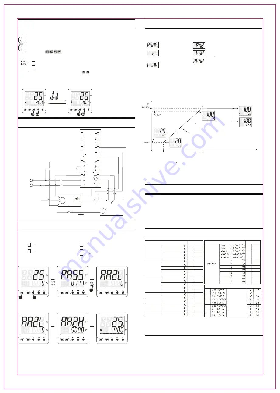
10. SV Panel setting and remote setting
10.1 Remote setting SV, use D1/D2 terminals at the back to set the SV
1: D1/D2 SV setting function was specified when order
2: PASS-0303 parameter RESV=1 or 2, enable the SV external setting
Condition:
4 SV can be assigned to SV1,SV2,SV3,SV4 under F01 menu
D1 open/D2 open: SV=SV1, D1 close/D2 open: SV=SV2
D1 open/D2 close: SV=SV3, D1 close/D2 close: SV=SV4
SV1,SV2,SV3,SV4 on the panel indicates respective SV value(except FT200)
10.2 Remote setting SV via external analong signal input from INP2 or INP3
GND
-
or
condition 1: remote SV via analong signal from INP2 or INP3 was specificed when order
2: parameter RESV=1 or 2 (under menu PASS-0303), enable remote SV function
PASS-0101 menu, LSPL corresponding to the lower limit SV when analog singnal at lower limit
USPL cooresponding to the higher limit SV when analog signal at higher limit
SV1 and SV2 indicator lights up at the same time indicate the SV is
being configured via external analog signal(except FT200)
10.3 Switch between SV remote setting and SV panel setting
Goes to PASS-0303 and set RESV=2, quick swtich between remote SV setting and panel SV setting enabled, enter into
remote SV mode after power on
SV panel set mode
Remote SV mode
Press F2 and F3 at the same time
for approxi 2 seconds to switch
back and forth between SV panel set
mode and SV remote setting mode
Only applicable when RESV=2(under
PASS-0303 menu)
11. Three wires motor valve control
This is only available for valve control version of controller
please specify if you need position feedback or not when order
with us,output: OP1 for valve direct acting (open), OP2 for valve
reverse acting(close),make sure to put the motor valve on the
intermediate relay or AC contractors,You can also goes to
PASS-0303 and set PFbK=0 and switch off the position
feedback function in case you’ve already ordered a controller
with position feedback feature, the motor valve travel
time must be specifed via rUCY parameter under PASS-0101
menu in a no position feedback case,Quick start meanu
parameter MVFb is a monitoring parameter for the valve
feedback value, this can be configured via parameter MoNI
under PASS-0303, the bargraphic can also be used to indicate
the feedback value, this
can be configured via
bEAM under
PASS=0303
1: No connection goes to terminals
16,17,18 for no feedback valve
2: Postive input on terminal 18 and
negative goes to terminal 17 for
analog feedback valve
Potentiometer feedback
Valve
close
Valve
open
Actuator
Fuel pipe
Fuel injection point
Thermocouple
Burner
Potentiometer
feedback
(object
being
controlled)
W
ir
e l
en
g
th
>
2
m
et
er
s
W
ir
e l
en
g
th
>
2
m
et
er
s
12. Positiion feedback caliberation and operation
GND
-
GND
-
+
5V
INP2
+
INP2
+
Condition
1: Position analong feedback via terminal INP2 ordered( only applicable for 3 wires motor valve or analog output controller)
2: PFbK=1, position feedback enabled for close loop control
General feedback signal, 1) standard analog signal, 2)Potentiometer feedback signal, specify when order
3 wires potentiometer as feedback source
Controller auto detect direct/reverse act
of the potentiometer
input +
input -
analog input
4-20mA, 0-5V input
from INP2 terminals
Auto caliberatioin on the position feedback
PV/SV mode
Password input
Position feedback caliberation
PV/SV mode, press SET and F3
at the same time PASS pop-up
Put PASS=0111
press SET to enter
Position feedback
“0" point caliberation
Position feedback
“maximum” point caliberation
PV/SV mode
Auto
Auto
1. 3 wires motor valve auto caliberation
Upper shows AA2L, OP2 light on, OP2 relay
pull-in, motor reverse act, lower display
changes along with the motor reverse act,
display switch to one at right after some
while, “0" point caliberation finished
2. Analog output controller
upper shows AA2L, OP1 output at 0%
value, lower display changes along with
the feedback signal,display switch to the
one at right after some while, “0"caliberation
finished
1.Upper shows AA2H, OP1 light on
OP1 relay pull-in, valve direct act
lower display changes along with the
direct act, display switch to the right
one after some while, caliberation finished
2.for analong output, upper shows AA2H,
OP1output 100%,lower display changes
along with the valve feedback signal,
display changes to the right after some
while, process finished
Caliberation finish, goes back to PV/SV
mode,these process always carried out
automatically, user shall only oberserve
the lower display changes, MVFb can be
used to monitor the feedback value,MoNI
under PASS-0303 used to define the
status of MVFb
Bargraphic % display can be used to
shows the feedback %, bEAM uner
PASS-0303 used to define the status of
the bargraphic display
13. Temp constant mode and ramp/soak mode
This is only applicable for programmable version of controller. specify when order
13.1 Parameters that involved
Assign the unit for timer
0: unit is second
1: unit is minute
Parameters under PASS-0101
0: standard type
1: temp constant mode
2: ramp and soak mode
Assign the temperature where timer kick-in
constant temp/ramp and soak start temp=SV-tSP
when PV>SV-tSP and stays for 5 seconds, program activated
Define the control status after timer finished
=0, PID stop working after timer finished
=1, PID continue the output after timer finished
power interruption or press F1 for 2 seconds can re-start
the program
F03 group of parameters
Ramp and soak mode,Ramp
is the temperature increase rate
degree per minute, degree/minut
Timer configuration
T1=0 means timer off
Parameter “Unit” under PASS-0303
Setting value
power on or
input SV value
alarm output when timer starts
alarm output when timer finish
PV> SV-tSP, stays for 5 seconds
lower display starts to indicate the timer
process, PRG light flashes
PV=SV+rAMP
output
continous
after timer
finish,PRG
lights on
output stop
after timer
finish
PRG light
on
END MODE
Temp
Time
Ramp and soak mode
lower display starts to indicate
the PV when ramp/soak mode activated
PRG light on
power on or
input SV value
5 seconds
Ramp period
Soak period
minute/second
13.2 Ramp and soak mode detailed working flow chart PMd=2
1. program execute: power-on, lower display shows SV, this will delay 5 seconds before the program starts, PRG lights on during the
ramp and soak process,lower display starts to indicate the PV value, PV increase gradually based on the preset ramp up rate
torwards to SV value
2. Timer kick-in: When PV >SV-tSP for at 5 seconds, timer kick-in, lower display shows the timer, PRG flashes,timer range is t1 value,
timer starts alarm and timer finish alarm can be configured, refer to PASS-0101 ALd1 and ALd2
3. Timer finish: when timer finish, PRG light on, based on PENd parameter under PASS-0101, output can be configured
as continoue working or stop, when alarm mode=18, alarm will be triggered after timer finish
4. program terminated: if PEND=0 configured, program ends after timer finish, lower display shows “End”
main output off, press F1 for 2 seconds can enter into STOP mode or active the program again
13.3 Temp constant mode working flow chart PMd=1
1. Program activate: lower shows SV, and heatup torwards SV immediately
2. Timer kick-in: when PV>SV-tSP, stays for 5 seconds, timer activated, lower display shows
timing process, PRG flashes,timer range is t1 value, an alarm can go off when timers starts by
configuring the ALd1 or ALd2=17 under PASS-0101
3. Timer finish: when timer finish, PRG light on, based on PENd parameter under PASS-0101, output can be configured
as continoue working or stop, when alarm mode=18, alarm will be triggered after timer finish
4. program terminated: if PEND=0 configured, program ends after timer finish, lower display shows “End”
main output off, press F1 for 2 seconds can enter into STOP mode or active the program again
14. RS-485 communication brief
15. Input sensors and range
(1) Communication based on modbus RTU, support 03 read command, 06 and 10
write command
(2) Communication format, 2 wires system, half-duplex, single drop connection
(3) Communication speed: 2400, 4800,9600,19200 baud rate, data format, 1 start bit+
8 data bit+parity(N,o.E)+1 /2 stop bit
(4) Support maximum 36 wirte command and 37 read command
(5) Detailed setting goes to PASS-0101 and locate parameter IdnO, bAUd, UCR parameters
(6) Refer to “COM-800-C1" for detailed communication protocol information
Input type
Code
Input type
Code
Input type
Code
The accuracy is not guaranteed for type S thermocouple in the range of 0-100
Remark 1: user can switch input between thermocouple and RTDs via software
Remark 2: analong input except 0-50mA, 10-50mV needs to be specified when order
FT20X
-
800
-
C1


