User Manual
EN
www.maxwell-digital.com
d
escription
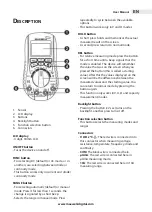
1. Sensor
2. LCD display
3. Buttons
4. Backlight button
5. Function selection button
6. Connectors
lCd display
•
4 digit, 18mm LCD
On/OFF button
•
Turns the device on and off.
FunC button
•
For selecting DC (default) or AC mode, or in
another case, selecting between diode or
continuity mode.
•
This button works only in current and diode/
continuity mode.
range button
•
For selecting automatic (default) or manual
mode. Press it for less than 1 seconds, the
change is signaled by a short beep.
•
Selects the range in manual mode. Press
repeatedly to cycle between the available
options.
•
This button works only in V and Ω modes.
HOld button
•
A short press holds and memorizes the actual
measured result on the screen.
•
A second press returns to normal mode.
rel button
•
For relative measuring mode press the button
for a short time until a beep signals that the
mode is enabled. The device will remember
the value that was on the screen when you
pressed the button (this is called a starting
value). After this the values displayed on the
screen will be the differences between the
measured values and the starting value. You
can return to normal mode by pressing the
button again.
•
This function only works in V, A, Ω and capacity
measurement modes.
Backlight button
•
Pressing the button (<2 sec) turns on the
backlight, another press turns it off.
Function selection button
•
This button selects the measuring modes and
ranges.
Connectors
•
V Ω Hz ºC -||-: The red wire is connected into
this connector when measuring voltage,
resistance, temperature, frequency, diode and
continuity.
•
COm: The black wire is connected here.
•
μama: The red wire is connected here in
μAmA measuring mode.
•
10a: The red wire is connected here in 10A
measuring range.


