background image

16 


4.5 

SPARE PARTS 


Maxwell recommends a modest quantity of spare 
parts to be ordered as familiarity with the windlass is 
developed during installation. Frequently smaller 
parts are lost during maintenance, so keeping spares 
(and spare tools) is recommended. 
We recommend the following list of spare parts to be 
carried on board: 
Part no. 

Description 

Qty 

3227 

Plastic Cap 

5953 

Disc Spring 

2311 

Retention Clip 

3150 

Key - Topworks 

4635  

Key - Gearbox 

7068  

Washer 

2310 

Spring 

SP0878 

Circlip 

 
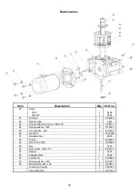
If you need any other spare part, please refer to the 
Appendix B for the correct part number and contact 
one of our distributors worldwide (Appendix E). 
When ordering spare parts, please also quote the 
serial number of the windlass. 


4.6 

TOOLS FOR MAITENANCE 


We recommend the following tools be kept on board 
for disassembling and assembling the windlass: 

• 

Set of metric hexagon keys 

  Ring / open end spanner 13, 17, 19mm and 

9/16” 

  Flat screw driver 10mm blade width 

  Circlip pliers 


Summary of Contents for VWC 2500

Page 1: ...2500 VWC VWCLP MANUAL ...

Page 2: ...ights reserved Patents pending Printed in New Zealand P19163 Rev 7 00 27 07 2010 Maxwell Marine International Ltd reserves the right to make engineering changes to all products without notice Illustrations and specifications not binding as to detail ...

Page 3: ...Y WARNINGS 3 2 LOWERING THE ANCHOR UNDER POWER 3 3 RETRIEVING THE ANCHOR UNDER POWER 3 4 LOWERING THE ANCHOR UNDER MANUAL CONTROL 3 5 RETRIEVING THE ANCHOR UNDER MANUAL CONTROL 3 6 OPERATING THE WARPING DRUM INDEPENDENTLY 4 0 MAINTENANCE 4 1 EVERY TRIP 4 2 EVERY THREE MONTHS 4 3 EVERY YEAR 4 4 RECOMMENDED LUBRICANTS 4 5 SPARE PARTS 4 6 TOOLS FOR MAINTENANCE 5 0 TROUBLESHOOTING APPENDIX A Dimension...

Page 4: ...ng used on board Correct fit of the chain to chainwheel is essential for reliable and safe operation of the windlass This can be guaranteed only when calibrated chain to a recognised international standard is used and the chain is correctly identified to Maxwell or if a chain sample is provided to Maxwell to develop a custom chainwheel The windlass is designed for use in conjunction with chain sto...

Page 5: ...configuration see description of Definition of rotation in Section 2 1 Picture 1 1 Picture 1 2 VWC Topworks VWCLP Topworks Chainwheels The chainwheel numbers consist of two parts main part number and suffix for example 3231 001 The main part number refers to the type of chainwheel and the suffix refers to size and type of chain Please refer to your closest Maxwell Marine agent or distributor Appen...

Page 6: ... ft min Maximum pull capacity 1135kg 2500lb Current at 350kg load 100A Current at stall 380A Motor power 1 5kW 2HP Weight of capstan 41kg 90lb Rated capacity and chain speed is based on the chainwheel for 10mm chain The performance may vary by up to 10 when other size chainwheels are used ...

Page 7: ... pocket is recommended If the anchor is not snug in the pocket it could cause damage to the pocket in a heavy seaway Ensure a minimum of 800mm 32 clearance between the end of spurling pipe and the chain piled up in the chain locker Picture 2 3 This will assist kinks which may develop in outgoing chain to shake free The chain must gravity feed into the locker If the chainpipe cannot be positioned d...

Page 8: ...equipment to beyond breaking strength of the chain The mounting area for the windlass must be perfectly flat and rigid Structural grade fillers can be used to level this area if initial flatness is inadequate Mounting area for the chain stopper should be prepared at the same time The chain stopper has to be installed at an appropriate height to ensure that chain lays horizontally when it comes out...

Page 9: ...er surfaces that are likely to seize after being in contact for a prolonged period of time Also ensure anti corrosive coating is liberally applied to the inside wall of the spacer tube 2 4 INSTALLING THE WINDLASS Refer to the drawing in Appendix B for help with identifying components and installing them correctly Extra care should be exercised when handling polished parts to avoid any damage to po...

Page 10: ... generously over the main shaft and keyway Insert key into the lower keyway on the main shaft Assemble the lower clutch cone making sure it sits nicely on the retention clips picture 2 5 Apply Lithium based marine grease generously to the conical surface of the clutch cone to assist with free falling the anchor Put the disc spring on top of the lower clutch cone turning its smaller diameter toward...

Page 11: ...of 90 C and sizes allow for a maximum 10 voltage drop over the total length Cable lengths given are from the battery terminal to the terminal on the motor via the solenoid box and then back to the battery Where a portion of cable runs through the engine room a size increase should be made as indicated After connecting the cables spray all terminals with anti corrosive waterproof coating CRC 3013 S...

Page 12: ...lug on the other end of cable and a matching waterproof socket which should be installed on a convenient location on the deck All units are supplied with detailed wiring instructions to assist installation Refer to wiring schematics in Appendix C for control circuits All control wiring should be done using no smaller than 1 5mm wire AWG 16 A manually re settable ignition proof 3A breaker or fuse s...

Page 13: ... keep fingers away from the chain Use clutch nut lever underneath and guarded by the chainpipe Always motor up to the anchor position before retrieving it from the bottom Do not use the windlass to pull the boat to the anchor If the anchor is fouled do not use the windlass to break it out With the chain stopper taking the load use the boat s engine to break the anchor loose When lowering the ancho...

Page 14: ... as sound practice to motor over the anchor position and so reduce chain tension This will also help the anchor to break out reduce the power consumption and reduce load on the windlass and deck gear Care should be exercised when docking the anchor to avoid damage to the anchor pocket Jog in the last meter 3 4 of the chain carefully seating the anchor home 3 4 LOWERING THE ANCHOR UNDER MANUAL CONT...

Page 15: ... The drum can be operated independently of the chainwheel and can be used to manage docking lines or a second anchor To use in this way proceed as follows Engage the chain stopper and or the pawl Fully disengage the clutch as described in Section 3 4 The drum may now be operated independently of the chainwheel Maxwell recommends all warping operations be controlled by the footswitch This makes it ...

Page 16: ... nipple installed grease bearing in the deckplate usingthe grease nipple Clean chromed surfaces with a cloth damp with kerosene After cleaning spray them with CRC 3037 Long Life or alternatively with CRC 6 66 or WD 40 Regular use of CRC3097 Long Life will assist in maintaining the bright chrome finish Re assemble in the reversed order Inspect the components below deck for corrosion chipped paint e...

Page 17: ...Gearbox Oils ISO 3448 VG 320 CASTROL Alpha MAX 320 SHELL Tivela oil SC320 MOBIL Mobilgear 632 BP MACH GR XP 320 Anti Corrosive Coatings CRC 3013 Soft Seal Boeshield T9 Lanocote Anti Seize Coating International Paints Res Q Steel Never mix greases use only one type If in doubt remove the previous lubricant and clean the parts thoroughly before applying the new one ...

Page 18: ...ring 2 2311 Retention Clip 2 3150 Key Topworks 2 4635 Key Gearbox 1 7068 Washer 1 2310 Spring 1 SP0878 Circlip 2 If you need any other spare part please refer to the Appendix B for the correct part number and contact one of our distributors worldwide Appendix E When ordering spare parts please also quote the serial number of the windlass 4 6 TOOLS FOR MAITENANCE We recommend the following tools be...

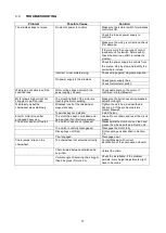
Page 19: ...ng Make sure the bolts have spring washers adjust bolt length Windlass runs but the chainwheel stays stationary Windlass runs but the chainwheel stays stationary Tighten the clutch up as described in Section 3 2 If the problem persists contact Maxwell Topworks key not installed Install the key Electric motor stops after prolonged heavy use The motor has been overloaded and has reached its critical...

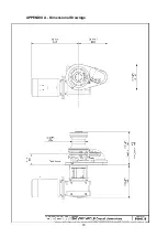
Page 20: ...18 APPENDIX A Dimensional Drawings ...

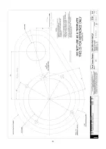
Page 21: ...19 ...

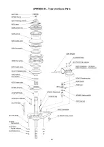
Page 22: ...20 APPENDIX B Topworks Spare Parts ...

Page 23: ...21 ...

Page 24: ... 44 Spring washer M8 4 SP0467 45 Flat washer M8 4 SP0428 46 Gearbox 1 P102089 47 Gearbox Key 1 4635 48 Circlip 1 SP0878 49 Hex Hd Nut M8 4 SP0366 50 Key 1 5116 51 Cap screw M6 x 25 4 SP0175 52 Spacer 1 5487 53 Adapter plate 1 4592 54 24V Motor 1 SP2960 55 Spring washer M8 4 SP0467 56 Motor Bolts M8 x 30 4 SP0279 Clutch nut handle 1 P20040 User s Manual 1 P19163 ...

Page 25: ...23 APPENDIX C Electrical Wiring Schematics ...

Page 26: ...24 ...

Page 27: ... original purchaser of the products only The benefits of the Warranty are not transferable to subsequent purchasers 6 Maxwell shall not be responsible for shipping charges or installation labour associated with any warranty claims 7 There are no warranties of merchantability fitness for purpose or any other kind express or implied and none shall be implied by law If any such warranties are nonethe...

Page 28: ......

Page 29: ...NOTES ...

Reviews: