background image

24 

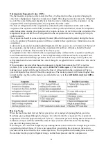
Thermostatic Expansion Valve (TXV) 

The thermostatic expansion valve meters the flow of refrigerant into the evaporator changing its 
state from a highpressure liquid to a lowpressure liquid. This drop in pressure causes the refrigerant 
to cool. The cooled refrigerant absorbs heat from the water circulating over the evaporator. As the 
evaporator fills with liquid refrigerant, the evaporator becomes colder. 
The flow of refrigerant into the evaporator is controlled by the temperature at the outlet of the 
evaporator. The expansion valve bulb, mounted to the top of the suction line, senses the evaporator 
outlet temperature causing the expansion valve to open or close. As ice forms on the evaporator, the 
temperature drops and the flow of refrigerant into the evaporator decreases, resulting in a drop in 
suction pressure. 
The evaporator should become completely flooded (filled with liquid refrigerant) during the freeze 
cycle. A completely flooded evaporator will have a uniform freeze pattern (ice formation across the 
evaporator). 
A starved evaporator (not enough liquid refrigerant) will have poor or no ice formation at the top of 
the evaporator, and the tube(s) exiting the evaporator will not frost. All tubes should be frosted 
approximately 5 minutes from the start of the freeze cycle. 
An expansion valve that is restricted or not opening properly will starve the evaporator resulting in 
lower than normal suction pressure. A low refrigerant charge will also starve the evaporator and 
cause low suction and discharge pressures. If not sure of the amount of charge in the system, the 
refrigerant should be recovered and the correct charge be weighed in before a defective valve can be 
diagnosed. 
If the evaporator is starved but the suction pressure is higher than normal, the TXV is not the 
problem, refer to the troubleshooting section. 

If the TXV sticks open 

or if the thermal bulb is not 

making good contact with the suction line, the flow of refrigerant into the evaporator will be too 
great and liquid refrigerant will flood the compressor. The suction pressure will remain higher than 
normal and the machine will remain in an extended freeze cycle. 

Ice will build evenly but will be 

very thick


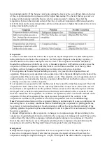
Hot Gas Valve 

When the machine enters harvest the hot gas valve coil is energized opening the hot gas valve. 
Discharge gas is pumped through the hot gas valve directly into the evaporator. The evaporator 
temperature will reach approximately 40°F (4.5°C). The suction pressure during harvest should be a 
minimum of 70 psi (4.8 bar) for R404a units or 50psi (3.4 bar) for R134a units. The discharge 
pressure will drop during harvest. 
If the hot gas valve does not completely open during harvest, there will not be enough hot gas in the 
evaporator to defrost the ice. If there is not enough hot gas entering the evaporator, the suction 
pressure will be lower than the above stated pressures. It is important when making this check that 
the machine has the proper refrigerant charge, normal head pressure and the compressor is 

Summary of Contents for MIM1000

Page 1: ...1 Automatic Ice maker Service manual MIM452 MIM600 MIM1000...

Page 2: ...Works 4 Water System 7 Wiring Connections and Controller 9 Exploding Drawing 12 TroubleShooting 14 Before Maintenance 14 Basic Checking 14 TroubleshootingGuide 15 Adjustment and Replacement 20 Advanc...

Page 3: ...t Water Filtration A water filter system should be installed with the ice machine Clearance Requirements Self contained air cooled ice machines must have a minimum of 6 inches 15cm of clearance at the...

Page 4: ...oth to remove any remaining residue If necessary remove the water distribution tube disassemble and clean with a bottlebrush Reassemble all components and repeat steps 4 through 7 as required to remov...

Page 5: ...5 Cooling System...

Page 6: ...ol the liquid refrigerant after passing through the condenser The drier and filter reduce possible dirt and moisture in the refrigerant The refrigerant expands in the evaporator cooling it so ice will...

Page 7: ...et tube 7 Floater valve 8 Water trough 9 Water pump 10 Water pump outlet tube 11 Water distribution tube 12 Evaporator Ice Mold 13 Ice full sensor 14 Drain pipe connector 15 Drain pipe hex nut 16 Drai...

Page 8: ...ugh to the water distribution tube The distributed water flows over the surface of the cold evaporator where the purest water is converted to ice The unfrozen water returning to the trough At the end...

Page 9: ...9 Wiring Connection...

Page 10: ...rks regularly to keep the lower temperature for lower ice melting The rest of the electric components are powered off The WHITE LED indicates the ice full status and the GREEN AND YELLOW LEDs together...

Page 11: ...e in the Ice Size Adjustment mode press the Clean button or the Mode button for the desired ice size Smaller ice setting By pressing the Clean button you can decrease the size of the ice cubes The FUL...

Page 12: ...12 Exploding Drawing...

Page 13: ...pipe 17 Water outlet pipe screw 18 water outlet pipe screw 19 Water inlet connector 20 foaming PE 21 top panel 22 compressor starting device component 23 compressor 24 discharge pipe1 25 suction pipe...

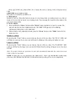
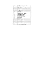
Page 14: ...ront panel 48 compressor base 49 left panel 50 knob 51 compressor base support 52 Water distributor tube 53 Water out of pump 54 water pump support 55 Water pump 56 Drain pipe 57 Drain pipe connector...

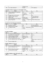
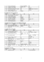
Page 15: ...he cycle of the icemaking and ice harvesting normal Does water run is the fan running and is the evaporator getting cold enough Check the water system especially at the connections Are there any water...

Page 16: ...16...

Page 17: ...17...

Page 18: ...18...

Page 19: ...19...

Page 20: ...20...

Page 21: ...e steps to reassemble Replacing the cooling system components To replace the condensing components see the Cooling System figure 1 Replacing the compressor and the compressor kit includes relay therma...

Page 22: ...condenser The refrigerant changes to a liquid when cooled The refrigerant in a liquid state passes through a filter drier The filter drier traps small amounts of moisture and foreign particles from t...

Page 23: ...proper voltage is supplied to the compressor and all wiring is properly connected If the compressor does not start and there is excessive amperage draw see locked rotor amps on compressor tag the com...

Page 24: ...l suction pressure A low refrigerant charge will also starve the evaporator and cause low suction and discharge pressures If not sure of the amount of charge in the system the refrigerant should be re...

Page 25: ...until the timer has energized Check the evaporator for areas where cubes are less developed than cubes in other areas If the cubes are all the same size coil separation is not the problem If there ar...

Page 26: ...cycle When the freeze timer is energized the machine is in the timed portion of the freeze cycle When the machine enters harvest the temperature rises but the amount of time the machine is in harvest...

Page 27: ...switch which detects its position When ice is sitting on the control the slideway faces down indicating that ice is present and disconnecting the circuit from the reed switch When the ice is removed t...

Page 28: ...re sensor of condenser 19 3 1851700501 Temperature sensor of evaporator 20 1858442400 Transformer 24 1854700800 Drain valve 28 1854601900 Expansive valve 29 1 1854704410 Hot gas valve body 29 2 185470...

Reviews: