background image

27

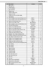
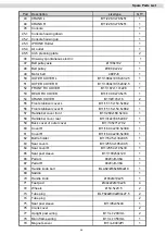
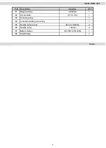
Spare Parts List

Part   Description

size/type                  QTY

1

Main frame

1

2

Upright post

1

3

Front stabilizer

1

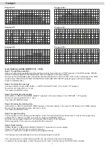
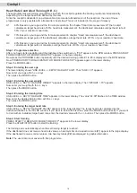
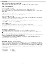
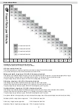
4

Rear stabilizer

1

5

Saddle post

1

6

Saddle sliding block

1

7

belt pinch roller

1

8

adjusting screw connection plate

2

9

Handlebars

1

10

Allen hexagon socket cap full thread screw

M6x10

4

11

Allen hexagon socket cap full thread screw

M8x20

7

12

Allen C.K.S. full thread screw

M6x15

2

13

Allen C.K.S. hollow screw

Ø8x33xM6x15

2

14

Allen hexagon socket cap half thread screw

       M

   1

  0

  x

  1

  3

  0

  x35

1

15

Allen flat head set-bolt

M12x70

2

16

Allen C.K.S. half thread screw

M10x110x20

2

17

Allen C.K.S. half thread screw

M10x50x20

1

18

Allen countersunk head full thread screw

M10x25

1

19

Allen C.K.S. full thread screw

M10x45

4

20

Philips pan head full thread screw

M4x10

6

21

Phillips C.K.S. sharp full thread screw

M5x15

8

22

Phillips countersunk head full thread screw

M5x20

3

23

Hex flange head full thread screw

5/16-18UNC-1

2

24

Philips C.K.S. self-tapping screw

ST4x16

25

25

Philips C.K.S. self-tapping screw

ST4x10

23

26

Philips pan head full thread screw

M5x15

5

27

Phillips countersunk head self-tapping screw

              S

   T  4  x  1 5

2

28

Flat washer

Ø6

7

29

Flat washer

Ø8

7

30

Flat washer

Ø10

8

31

Spring washer

Ø8

7

32

Spring washer

Ø10

6

33

Circlip for shaft

Ø20

1

34

Circlip for shaft

Ø25

1

35

Hex self-locking nut

M8

4

36

Hex self-locking nut

M10

3

37

Hex nut

M10

5

38

Hex nut

M24xP1.5

1

39

Deep groove ball bearing

6004ZZ

2

40

Deep groove ball bearing

6005ZZ

2

41

Belt compress powder in tube

Ø13xØ8.5x8.4

3

42

Flat washer

8612-07

2

Summary of Contents for RunMAXX 90 PRO

Page 1: ...ENG MAXXUS 90 PRO Bike I N S TA L L AT I O N O P E R AT I N G M A N U A L...

Page 2: ...ploded Drawing 26 Spare Parts List 27 29 Warranty 30 31 Service Contract 2019 MAXXUS Group GmbH Co KG All rights reserved All rights reserved This publication may not be reproduced stored in a retriev...

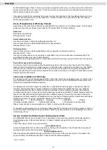
Page 3: ...n ground both in operation and at rest Any uneven surfaces must be removed or made good It is recommended permanently to place a MAXXUS Floor Protection Mat under the device to protect damageable oors...

Page 4: ...4 Overview of the Device Handlebars Pulse sensors Seat Pedal Cockpit Tablet holder Handlebar Shaft Stand with Transport Rollers Stand with transport handle...

Page 5: ...16 Hexagon socket screw M10x110 2 pieces Part 15 Grub screw M12x70 2 pieces Part 30 Washer 10 6 pieces Part 11 Hexagon socket screw M8x20 3 pieces Part 31 Spring washer 8 3 pieces Part 20 Phillips sc...

Page 6: ...structions for the individual assembly steps The installation of the training device must be carried out by responsible adults Carry out the installation of your training device with two adults in a l...

Page 7: ...screws 15 already inserted Attention When inserting and fastening the handlebar stem 2 make absolutely sure that you do not crush or damage the cables Step 4 Mounting the cockpit Connect the cockpit c...

Page 8: ...s M8x20 11 three spring washers 8 31 and three washers 8 29 Attention When inserting and attaching the handlebar 9 make absolutely sure that you do not crush or damage the cables Step 6 Fitting the ha...

Page 9: ...eath the saddle on the saddle tube and fix them with two pan head screws M4x10 20 each Step 9 Mounting the pedals Insert the thread of the right pedal 67 into the receptacle of the right pedal arm and...

Page 10: ...into electricity and used to power the cockpit and the braking system Switching on the cockpit As soon as you start pedalling the cockpit switches on automatically Switching off the cockpit The cockpi...

Page 11: ...the pedal posi tion so that the right pedal arm is pointing vertically down and the right pedal is at the lowest point of its radius of motion Now sit on the seat and place the heel of your right foo...

Page 12: ...ing your training device back into operation after a long period of non use make sure that all fasten ings are secure WARNING Before starting cleaning maintenance and or repair work the exerciser must...

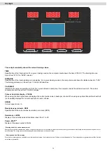
Page 13: ...value in beats per minute When using an optional transmitter chest belt not included displays the current heart rate in beats minute SPEED Current speed in km h Revolutions per minute RPM Speci catio...

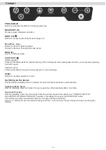
Page 14: ...ing pauses the current training RESET Button for resetting all values to zero Switching on the device Shortly after the pedalling motion is started the instrument panel switches on automatically Switc...

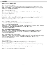
Page 15: ...TIME appears in the lower display The value 24 00 flashes in the TIME window Now enter the desired training time with the keys Then press the MODE button Step 4 2 Entering the training distance USE LE...

Page 16: ...press the MODE button Step 3 Entering the user weight USE LEVEL KEYS TO ADJUST WEIGHT appears in the lower display Then WEIGHT 70 appears Now enter your weight with the keys Then press the MODE butto...

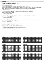
Page 17: ...hen press the MODE button Step 4 Entering the training time USE LEVEL KEYS TO ADJUST TIME appears in the lower display The value 10 00 flashes in the TIME window Now enter the desired training time wi...

Page 18: ...s displayed in the RPM window Now PRESS START FOR QUICKSTART OR MODE FOR SETUP appears again in the lower display Press the MODE button Step 2 Entering the user age The lower display shows USE LEVEL K...

Page 19: ...body fat percentage With this type of measurement an electronic pulse is sent through the body via the hand sensors Since body fat is not or only very poorly conductive the percentage of fat in the bo...

Page 20: ...25 carbohydrate and 5 protein Fat burning target zone 60 to 70 of the maximum heart rate This training zone is suitable for athletes and sports people who aim to lose weight Training in this zone the...

Page 21: ...everal people If the display of the pulse does not work only in individual cases the device is not defective In this case we recommend the use of a chest belt to achieve a permanently correct pulse di...

Page 22: ...Do not just get o your training device immediately the training session is nished Like with the warm up stage you should continue for 3 5 minutes at minimum resistance to cool down After training you...

Page 23: ...most people have training goals such as weight reduction cardiac exercise training improvement of physical con dition stress reduction etc to strive for training intensity to meet these goals should b...

Page 24: ...properly and in an environmentally sound manner Batteries Re chargeable Batteries if present in the device According to the Batteries Directive you as end user are legally obliged to return all used b...

Page 25: ...ust the foot stands Check if the screws at the articu lated joint between the pendulum tubes and the pedal arms are tightened securely My feet fall asleep during training The reason for this is often...

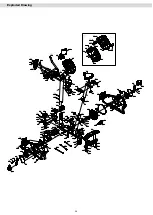
Page 26: ...26 Exploded Drawing...

Page 27: ...d screw M10x25 1 19 Allen C K S full thread screw M10x45 4 20 Philips pan head full thread screw M4x10 6 21 Phillips C K S sharp full thread screw M5x15 8 22 Phillips countersunk head full thread scre...

Page 28: ...56 Front stabilizer cover R B11 151 5x154 5x66 2 1 57 Handlebar cover front B11 289x168 5x144 1 58 Handlebar cover rear B11 312x168 5x88 7 1 59 Back cover of outer cover B11 135x71x79 2 1 60 Cover R...

Page 29: ...wiring L 600mm 1 82 Accumulator E11 L 100 1 83 Console wiring 1 84 Console handle pulse wiring 1 85 Handle pulse wiring B11 L 1000mm 2 86 Handle pulse 133mm 2 87 Battery holder B11 591x154 5x50 1 88...

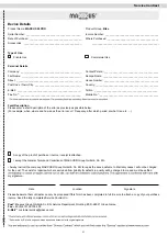
Page 30: ...for your training device starts on the date of purchase and applies solely to products which were purchased directly from the MAXXUS Group GmbH Co KG or one of the MAXXUS Group GmbH Co KG direct and a...

Page 31: ..._____________________________ Tel No _____________________________________________ Mobile No __________________________________________ Fault Description Please enter a short description of the error...

Page 32: ...Maxxus Group GmbH Co KG Nordring 80 D 64521 Gross Gerau Germany E Mail info maxxus de www maxxus com...

Reviews: