2202G1JE-DA-M-N_2010.01.
2 Configuration and Specification of Compressor
Reciprocating Compressor M Series
2.1 Configuration of Compressor
2-5
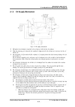
2.1.3 Oil Supply Mechanism
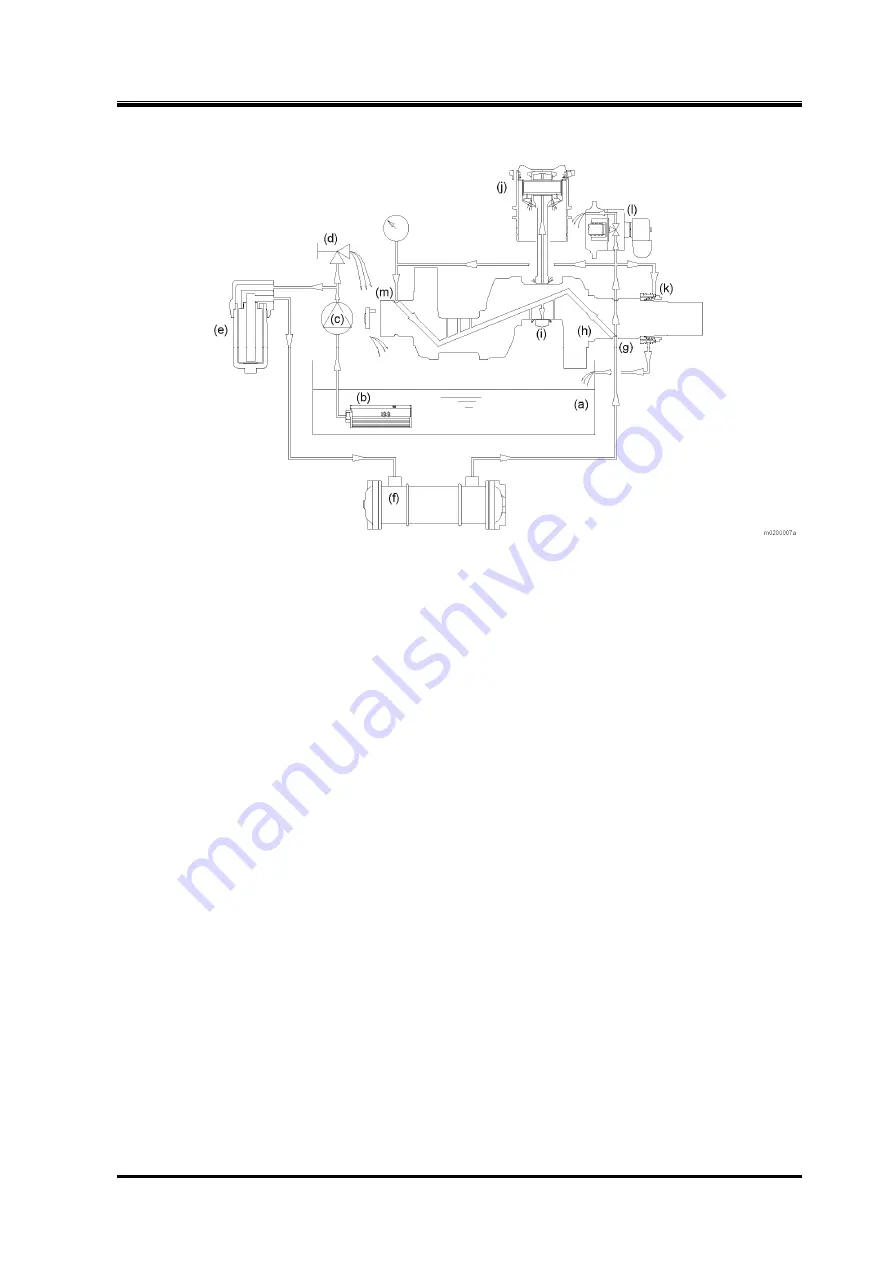
Fig. 2-11 Oil supply mechanism
1.
Refrigerant oil is retained as required in the oil tank (a) at the bottom of crankcase.
2.
When the oil pump (c) is driven by the crankshaft, refrigerant oil in the oil tank (a) is suctioned via the oil
strainer (b).
3.
The refrigerant oil is pressurized by the oil pump (c), and pumped into the oil pressure regulating valve (d)
and oil filter (c).
The oil pressure regulating valve (d) bypasses part of refrigerant oil via the oil tank so that the difference
between pressure in the oil tank (suction pressure) and oil supply pressure is maintained at a constant
value.
4.
The refrigerant oil filtered by the oil filter (e) is discharged from the crankcase to outside of the machine
and passes the oil cooler (f).
5.
The refrigerant oil cooled by the oil cooler (f) enters the crankcase. Then, it passes through the main
bushing on seal side (g) and enters the oil supply opening on the crankshaft (h).
6.
The refrigerant oil which passes the crankshaft (h) lubricates the crank pin (i), and passes the oil supply
line in the con rod. Then it lubricates and cools the cylinder (j) (inner wall of the cylinder, piston ring,
piston pin and bearing on the connecting rod small end).
7.
The refrigerant oil which passes through the main bushing on seal side (g) passes the shaft seal (k),
capacity control mechanism (unloader) (l), and the oil supply line in the case. Then, it is divided to be
supplied to the main bushing on pump side (m).
1)
The refrigerant oil which lubricates the shaft seal (k) returns to the oil tank.
2)
The refrigerant oil which lubricates the main bushing on pump side (m) enters the oil supply opening
on the crankshaft (h), then lubricates and cools the crank pin (i) and other parts.
3)
The refrigerant oil which is supplied to the capacity control mechanism (unloader) (l) passes the oil
supply groove on bearing head and oil supply opening on crankcase. Then it is supplied to each
solenoid valve unloader cover integrated.
When the solenoid valve is energized (ON), refrigerant oil enters the unloader cylinder and
presses the unloader piston, and then the unloader mechanism becomes loaded. At this time, the
oil flow stops. However, the unloader piston retains the position by being pressurized
continuously.

