2202G1JE-DA-M-N_2010.01.
3 Installation
Reciprocating Compressor M Series
3.2 Installation Works
3-11
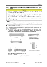
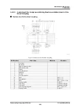
Centering and Attachment of Direct Couplings
The attachment positions of compressor and motor are designated according to the center distance appropriate
for attachment of couplings. Also, the difference of center core heights is within 0.1 mm by machining process of
frames.
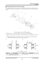
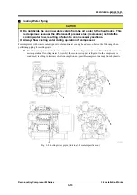
Fig. 3-6 Development view for the direct coupling parts
To align the center cores, correct the parallelism and deviation between left and right shafts.
1.
Retain the compressor on the frame with bolts, and attach the flywheel (a) to the crankshaft with mechlock
(b).
2.
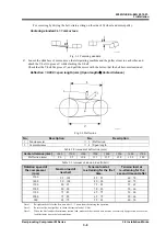
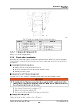
Set the dial indicator on the motor axle using a magnetic stand or others, so that the probe contacts the
external diameter and surface of the flywheel (a) on the compressor side.
Fig. 3-7 Measurement of axle core
Symbol
Description
No.
Description
A
Measurement of core deviation
1
Dial indicator
B
Measurement of angle deviation

