background image


10


e) 

Adjust the height of the top holding jaw so that it securely holds 

the second-to-last pot at the top edge of the pot. 


f) 

Adjust  double  pot  receptacles  2-

3  mm  below  the  upper  pot’s 

edge.  


g) 

Adjust the height of the pot dispenser. 

The bottom edge of the last pot in the dispenser should be 10 

– 

20 mm above a pot already positioned in the pot receptacle. 


h) 

Adjust  the  guide  rail  approx..  3-4  cm 

to  the  lower  pot’s  edge 

with enough play (reduce play at the drill). 


Summary of Contents for TM 2400DR

Page 1: ...Issue date 01 08 2020 V1 7 Before the initial start up read and keep at the machine for future use Operating instructions Potting machine TM 2400DR ...

Page 2: ... Installation 1 General notes 2 Installing the machine 3 Measures for the machine s stability against overturning 4 Disassembly and disposal of the machine 5 Initial start up 1 Check prior to first start 2 Starting the machine for the first time 3 Stopping the machine 6 Operation 1 Normal operation 2 Shutting down the machine 3 Measures prior to and after a longer shutdown 7 Malfunctions 1 Behavio...

Page 3: ...achine is not used in accordance with the regulations the safe operation of the machine is not guaranteed The usage for intended purpose involves the reading of the operating instructions and the compliance of the regulations specially safety regulations stated in it Furthermore every inspection and maintenance should be performed in specified time For damages that are originated from the usage fo...

Page 4: ...4 2 Structure Plan view of potting machine 2400DR back right left front ...

Page 5: ...eing there A controlled conveyor belt is installed into the soil hopper which forwards the soil always towards the elevator The turntable is inched and a drilling motor being synchronous with the inching mechanism drills a hole into the soil that s inside the pot by means of a replaceable drill One or several person s standing around the machine may plant plants into the pots Plant holding trays m...

Page 6: ...er Machine type Potting machine Series 2400DR Length width height 410 190 195 cm Weight 1 500 kg Working height approx 92 cm Power connection 400V 50Hz 5 pole Power input 3 kW Pot size 8 13 cm diameter for round and square pots Capacity of soil hopper 1 500 litres 2 200 3 000 4 500 litres on request Production speed Up to 7 000 pots hour with double pot holder Usable drill sizes 2 13 cm larger dri...

Page 7: ...pressure plate Chrysanthemum plate Plates for pouring edge Roller conveyor and roller curves Counting device Various belt storage dispensers Automatic pot transport in combination with conveyor belts Broadening devices and attachments for soil hoppers Trailer coupling Stainless steel elevator buckets Important note When placing repeat orders for accessories and spare parts make sure to have inform...

Page 8: ...O 13849 1 2015 EN ISO 13850 2008 Safety of machinery Emergency stop Principles for design ISO 13850 2006 EN ISO 13857 2008 Safety of machinery Safety distances to prevent hazard zones being reached by upper and lower limbs ISO 13857 2008 EN ISO 14119 2014 Safety of machinery Interlocking devices associated with guards Principles for design and selection ISO 14119 2013 EN 349 1993 A1 2008 Safety of...

Page 9: ...ffect the technical specifications given in the Operating Instructions or the intended use i e change the machine substantially will invalidate this EU Declaration of Conformity Heidenheim 01 08 2020 Geschäftsführer Managing Director ...

Page 10: ...tion section the machine is only operated when in flawless working order and especially that the working order of the safety equipment is regularly checked the Operating Instructions are always available in legible condition and complete at the location where the machine is used only sufficiently qualified and authorised personnel operate service and repair the machine these personnel are regularl...

Page 11: ...the safety instructions are meant to point out unavoidable residual dangers that exist when dealing with this machine These residual hazards relate to People The machine Other things and objects The environment The following safety symbols are used in these Operating Instructions This symbol indicates that there are dangers to the machine things and the environment but that no dangers to people ar...

Page 12: ...t reasons it is not possible to completely cover the compost hopper it is not allowed to reach into the compost hopper to push in more soil for example because when doing so there would be a danger of getting caught by the scraping chain it is not allowed to get into the compost hopper while the machine is running it is not allowed to reach into the turntable or pot dispenser while the machine is ...

Page 13: ...rotating assembly there is a potential hazard of getting stuck in there due to carelessness or wearing further additional clothing or jewellery In case of malfunctions during the work flow it is forbidden to touch the running machine in order to resolve the malfunction It must always be possible to access the emergency cut off switch The emergency cut off switch should always be located on the rel...

Page 14: ...at is involved and are authorised to do so These individuals have to know and act in accordance with the Operating Instructions The respective authorisations for the operation personnel must be clearly prescribed In addition to this special qualifications are required for the following activities Operation personnel being trained may at first only work with the machine under the supervision of an ...

Page 15: ...he machine the following special dangers must be expected Suspended loads can drop which would be a lethal danger never go under suspended loads If load lifting equipment other than that specified here severe damage to the machine may result 1 Transport When the machine is transported special care shall be taken to avoid damage of the machine during loading or unloading During transport fixings ac...

Page 16: ...ver an inclined plane it is necessary to completely empty the soil hopper to make sufficient safety precautions in order to prevent the machine from accidentally rolling away Such precautions may include enough personnel to secure the wheels using a wedge and so on 3 Storage When the machine or its parts are not reassembled right after transport then they shall be carefully stored on a protected a...

Page 17: ... c Be sure that enough space is assured for feeding and filling pots Same care shall be taken in case of machines connected in front of or behind it d In order to capacity of the machine to be used efficiently it is suggested the soil mixture seedling plants pots trays to be prepared on the best place and in sufficient quantity It is not suggested to under estimate job to remove and transport the ...

Page 18: ...machine using the pedestals 3 Measures for the machine s stability against overturning There is no need to carry out other activity for erecting the machine than it is described in section 4 2 4 Disassembly and disposal of the machine After completion of its full time of operation the machine must be duly separated from energy supply systems and disposed of according to valid legal regulations ...

Page 19: ... the machine Before the first start up check the electrical connections Activate all the safety equipment and EMERGENCY SHUT OFF switches before the initial start up Also read the section General Safety Instructions 1 Check prior to first start Prior to starting up the machine the following must be checked are all safety devices available was the machine damaged during transport all visible bolted...

Page 20: ... electrician to change phases at the connecting cable Plates of the elevator shall be forwarded from bottom towards top seeing from side of soil hopper Care shall be taken on the following With the potentiometer Soil means turn to the right larger amount of soil and more speed turn to the left smaller amount of soil and less speed Warning Switch position to right elevator and conveyor belt are mov...

Page 21: ...21 Flexible start stop with emergency cut out Emergency stop 1 1 Main switch 2 Soil 3 Rotating assembly 4 Drill 5 Scraper brush option 6 Socket outlet belt storage Socket outlet belt connection ...

Page 22: ...machine There are two ways provided to switch off the machine a In normal case by switch Stop mounted on the swinging cable b In emergency case by Emergency Stop switch Note See also section 6 2 Shutting down the machine ...

Page 23: ...sport Plant feeding and unloading Pot preparation Use the shortest transport routes b Adjusting or shifting the pot turntable Attach reversible ratchet to shifting spindle and open adjustable pot holder by turning it anti clockwise Pot supports always remain at the same height Reversible ratchet at the shifting spindle Turn to the left pot holder goes down Turn to the right pot holder goes up ...

Page 24: ...er in such a way that excessive soil is scraped from the pot Shifting of the scraper takes place via the hand wheel from outside clockwise higher anti clockwise lower Adjust lower scraper brush in such a way that it cleans the pot support Adjust upper scraper brush in such a way that it cleans the clamps of the pot holding discs ...

Page 25: ...ut of the machine by opening the soil flaps If the soil heap gets to high in front of the soil flap opening the potting machine must be pulled back a bit Cleaning of the elevator deflection also takes place by means of the soil flap openings d Adjusting drill depth and pressure intensity of down holders After the size of the soil drill and the down holder matching it are fixed the drilling depth m...

Page 26: ...ing depth by using an empty pot Drilling depth may be adjusted by shifting the rod in the sleeve and fixing them to each other by means of the threaded pin Then make a test drilling with pot filled up with soil and check the drilling depth readjust if it is required When soft plastic grided or Jiffy type pots are used pressing force of the press plate shall be set by using clamping pieces ...

Page 27: ...ply of soil from the soil hopper to the elevator takes place by means of a continuous rubber conveyor belt running on carrier rollers in the soil hopper There a 2 options to control the soil amount to be fed I By setting different potentiometer positions on the elevator and rubber conveyor belt to the right clockwise large amount of soil to the left anti clockwise small amount of soil Caution Righ...

Page 28: ... set compactness of the soil in the pot This depends on 1 Drilling in or out the soil mixture 2 Setting the filling quantity by setting the drawer 3 Type and size of pressing plate Comment to 1 Depending on the relevant setting of the drill motor s reverse switch you can operate an anti clockwise or clockwise rotation of the drill anti clockwise rotation is possible only with the standard drill Wh...

Page 29: ... e g 6 cm dia drill with pressing plate hole dia of 7 cm is small then only a few quantity of soil is removed and the filled soil is compact When this gap is larger e g 6 cm dia drill with pressing plate hole dia of 9 cm larger quantity of soil is removed and the filled soil is less compact The pressing plate with soil addition leaves a soil heap on the pot which may be compacted by repressing Spe...

Page 30: ...30 h Soil chute Adjustment of height Adjustment of inclination i Rotating brush with motor option Adjustment from outside ...

Page 31: ...inated the machine may be started by pressing push button Start 3 Measures prior to and after a longer shutdown a Before a long shutdown Clean carefully the machine Grease and oil certain parts of the machine according to maintenance plan Protect against dirt and moisture to be covered Disconnect the machine from power lines electricity compressed air b After a long shutdown Grease and oil certain...

Page 32: ... can result in injuries to people as well as damage to the machine In case of unprotected manual operation there is an increased risk of injuries through bruising 1 Behaviour in case of malfunctions If any malfunctions should occur while the machine is in operation proceed as follows 1 Stop the machine either using the STOP button or EMERGENCY SHUT OFF depending on the situation 2 When necessary f...

Page 33: ...ective Replace it Belt loses it s way Readjust it Drill 2Q2 2Q3 or 2Q4 motor protection switches cut off Drive is mechanically overloaded because of Drill is too large Change drill Drilling depth too large Readjust it Rotating direction Check it Drive is defective Replace it Motor protection switch is defective Replace it Motor brushes 2Q5 motor protection switch cut off Drive is mechanically over...

Page 34: ...y unit that is under pressure Only Mayer GmbH Co KG may ever manipulate the machine s control programme All un recycled operational materials lubricants and supplies must be disposed of in an environmentally friendly manner Also read the section General Safety Instructions When carrying out maintenance on the machine the following special dangers have to be expected Installing incorrect spare part...

Page 35: ...may be retensioned by means of tensioning bearings located on two sides of the elevator Check regularly if the chains are tensioned properly When the chain is too loose the plates may jam with edge of the housing Overtensioned chain requires an excess of driving power and causes too quick wear When the chains are retensioned both of them shall have the same tightness With the soil hopper being com...

Page 36: ...belt may be adjusted by means of tensioning nuts located at end of soil hopper It is important that both sides of the belt are tensioned by the same force Beyond the above care shall be taken on grooves of driving and guiding drum not to be filled up with soil Regularly clean the grooves when it occurs Generally the rubber belt requires no retensioning Follow the maintenance schedule ...

Page 37: ...of drilling unit daily Check safety instructions for sound condition weekly Check tension of elevator chain weekly Clean chains and buckets weekly Check and retighten if necessary drive chain of drilling stand monthly Grease shifting roll s groove and drive chains quarterly Grease 2 times rotating assembly brakes half yearly ...

Page 38: ...38 Grease holding down bar at drill yearly Grease all bearings fitted with grease nipples yearly Retighten rubber conveyor belt soil hopper after repair works ...

Page 39: ...39 9 Part list ...

Page 40: ...parts which we do not manufacture ourselves e g motors we can only accept liability for the same scope and length of time which the subcontractor has accorded to us Any replaced parts shall become our own property No warranty claims can be accepted if the fault occurs as a result of the customer having mistreated or neglected the products delivered by us made modifications or undertaken repairs in...

Page 41: ...during the delivery period provided that the purchased object is not thereby significantly altered rendered less effective or reduced in value and the customer can reasonably be expected to accept the modifications You have chosen to purchase a product of true quality We wish you every success with your product We would be most grateful if you would recommend our products to others Thank you Your ...

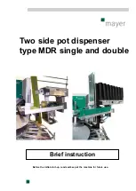
Page 42: ...Before the initial start up read and keep at the machine for future use Brief instruction Two side pot dispenser type MDR single and double ...

Page 43: ... Starting the pot dispenser 3 Stopping the pot dispenser 3 Operation 1 Normal operation 2 Measures prior to and after a longer shutdown 4 Malfunctions 1 Behaviour in case of malfunctions 2 Possible malfunctions and trouble shooting 5 Maintenance 1 General notes 2 Inspection and preventive maintenance 3 Maintenance schedule 6 Part list ...

Page 44: ... not used in accordance with the regulations the safe operation of the machine is not guaranteed The usage for intended purpose involves the reading of the operating instructions and the compliance of the regulations especially safety regulations stated in it Furthermore every inspection and maintenance should be performed in specified time For damages that are originated from the usage for not th...

Page 45: ...4 2 Functional description ...

Page 46: ... type Two side pot dispenser Series Type MDR double Length width Approx 60 60 cm Height with storage bracket Approx 50 cm Height without storage bracket Approx 110 cm Weight 30 kg Types of drive Pneumatic using compressed air cylinders pressure min 8 bar Pot size Round pots 8 13 cm external diameter Available accessories for an additional charge Mayer compressed air ejector Sets of jaws clamping f...

Page 47: ...ENCY SHUT OFF switches before the initial start up Also read the section General Safety Instructions 1 General notes The pot dispenser has been calibrated at our factory and its functions tested for the entire range of pot sizes However changes to techniques and material composition in the manufacture of deep drawn plastic pots can cause pots which have functioned without problems in the pot dispe...

Page 48: ...art to operate automatically as soon as the turntable of the potting machine begins to run 3 Stopping the pot dispenser The pot dispenser stops as soon as the potting machine s turntable comes to a standstill if the cylinder has already begun to move it will stop as has soon as it has reached its final position ...

Page 49: ...ncy power off Only the operating personnel of the machine can stand at the pot dispenser during operation You should also read the General safety specifications chapter The pot dispenser can be operated only from the prescribed work sites When operating the pot dispenser the following special dangers must be expected Usage not for the intended purpose can result in personal injury or damages of th...

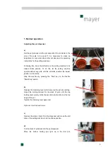
Page 50: ... the drill slide reaches the lowest position on its stroke Stop the machine by pressing the Stop key on the flexible Start Stop switch b Release the clamping lever which secures the pot size setting Adjust the holding bracket for the stack of pots until the top holding jaw securely holds the second to last pot below the top edge of the pot Tighten the clamping lever again 4x Optional Use the hand ...

Page 51: ...just double pot receptacles 2 3 mm below the upper pot s edge g Adjust the height of the pot dispenser The bottom edge of the last pot in the dispenser should be 10 20 mm above a pot already positioned in the pot receptacle h Adjust the guide rail approx 3 4 cm to the lower pot s edge with enough play reduce play at the drill ...

Page 52: ...3 mm j Run the dispenser and potting machine at a low potting speed and watch how the pots are fed in Stop the machine before making any corrections to the setting if any are necessary Set the potting machine to the required working speed if the pots are being fed in correctly ...

Page 53: ...g shutdown Clean carefully the pot dispenser Grease and oil certain parts according to maintenance plan Protect against dirt and moisture to be covered b After a long shutdown Grease and oil certain parts according to maintenance plan Visually check the pot dispenser ...

Page 54: ...ces can result in injuries to people as well as damage to the pot dispenser In case of unprotected manual operation there is an increased risk of injuries through bruising 2 Behaviour in case of malfunctions If any malfunctions should occur while the pot dispenser is in operation proceed as follows 1 Stop the machine either using the STOP button or EMERGENCY SHUT OFF depending on the situation 2 W...

Page 55: ...ed air ejector Either no pots or several pots at once fall into the pot receptacle Incorrect dispenser setting Correct the setting Recycled pots do not run well on the pot dispenser Incorrect bottom holding jaw Use a special holding jaw Pot dispenser does not operate No pressure Check the pressure Sensors are misadjusted Adjust sensors Plug connections Check plug connections ...

Page 56: ... that is under pressure Only Mayer GmbH Co KG may ever manipulate the pot dispenser s control programme All un recycled operational materials lubricants and supplies must be disposed of in an environmentally friendly manner Also read the section General Safety Instructions When carrying out maintenance on the pot dispenser the following special dangers have to be expected Installing incorrect spar...

Page 57: ...For service or repair work order our customer service at one of our service workshops Spare parts have to meet the technical requirements of the machine s manufacturer This is guaranteed with original spare parts from MAYER 2 Inspection and preventative maintenance Grease and clean machine regularly ...

Page 58: ...17 6 Part list ...

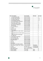
Page 59: ...ing ring DV5 0 01 013 1 1 14 fastening block for lower retainer jaw DV5 0 01 014 1 1 15 fastening block for central retainer jaw DV5 0 01 015 1 1 16 fastening block for fixed upper retainer jaw DV5 0 01 016 1 1 17 fixed upper retainer jaw DV5 0 01 017 1 1 18 lower retainer jaw DV5 0 01 018 1 1 19 central retainer jaw DV5 0 01 019 1 1 20 retaining plate DV6 0 01 020 0 1 21 disc DV5 0 01 021 2 8 23 ...

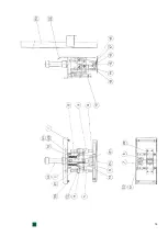
Page 60: ...19 ...

Reviews: