Installation and Operational Instructions for
EAS
®
-dutytorque Type 404_._ _400
Sizes 2
– 9
(B.4.3.1.ATEX.EN)
06/10/2016 TK/GH/SU
Chr. Mayr GmbH + Co. KG
Eichenstraße 1, D-87665 Mauerstetten, Germany
Tel.: +49 8341 804-0, Fax: +49 8341 804-421
Page 10 of 15
Torque Adjustment (Figs. 3 and 4 / Page 4)
Set the limit torque M
G
for overload on the clutch by changing the
cup spring pre-tension on each overload element (6) according
to the Adjustment Diagram.
On the clutches the adjusting nut (9) is adjusted by turning it in
the overload element (6) using an open-end wrench.
Wrench opening values of the adjusting nut (9):
Wrench opening 19 for Sizes 2 and 3
Wrench opening 30 for Sizes 4, 5 and 6
Wrench opening 41 for Sizes 7, 8 and 9
During torque adjustment, please ensure that
all overload elements (6) on the clutch are
evenly adjusted!
Torque Adjustment:
Type 404_._0400 (Fig. 3)
Determine the limit torque M
G
for overload.
Please find the dimension “a” from the Adjustment Diagram
included in clutch delivery.
This dimension is equal to the required limit torque M
G
.
Remove the cap screws (11) and the lock washers (10), so
that the adjusting nuts (9) can be turned.
Set all overload elements (6) by turning the adjusting nut (9)
to the dimension “a” found in the Adjustment Diagram.
Secure the adjusting nuts (9) against turning using the lock
washers (10) and the cap screws (11).
Tighten the cap screws (11).
Type 404_._1400 (Fig. 4)
Determine the limit torque M
G
for overload.
Please find the dimension “a” from the Adjustment Diagram
included in clutch delivery.
This dimension is equal to the required limit torque M
G
.
Unscrew the switching disk (14) and remove the
countersunk screws (13) and distance bushings (12).
Remove the cap screws (11) and the lock washers (10), so
that the adjusting nuts (9) can be turned.
Set all overload elements (6) by turning the adjusting nut (9)
to the dimension “a” found in the Adjustment Diagram.
Secure the adjusting nuts (9) against turning using the lock
washers (10) and the cap screws (11).
Tighten the cap screws (11).
Tighten the countersunk screws (13) via the switching disk
(14) and the distance bushings (12) in the bolts (7).
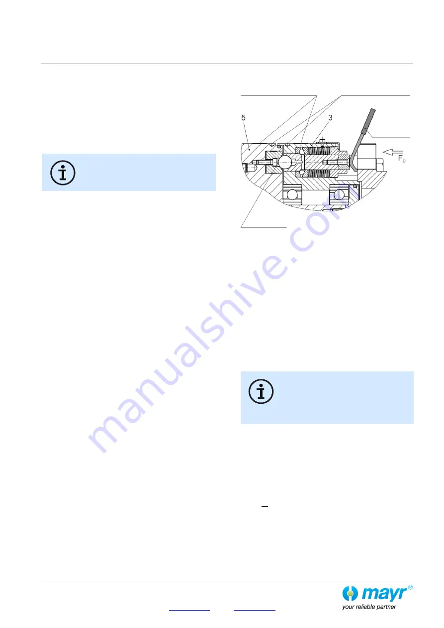
Re-engagement (Fig. 7)
Fig. 7
In order to make the clutch ready for operation again after
overload occurrence, the bolts (7) in the overload elements (6)
must be re-engaged.
Both of the yellow guideline signs for regaining the synchronous
position (due to balance quality) on the outer diameters of the
element flange (3) and the pressure flange (5) must align with
each other (Fig. 7).
Re-engagement takes place by placing axial pressure on the bolt
end of each overload element (6).
Depending on the equipment available, the accessibility of the
installation point etc., re-engagement can be carried out in the
following ways:
Manually, using a suitable tool.
By using an engagement mechanism. The engagement
procedure can also be automated using pneumatic or
hydraulic cylinders.
On Type 404_._1400 (Fig. 4, page 4), re-
engagement takes place by placing axial
pressure via the switching disk (14) on the bolt
end of each overload element. Inaccurate
application of the lever tool onto the bolt end
can lead to the switching disk (14) bending,
and thus to a risk of ignition.
The level of engagement force required is dependent on the set
limit torque for overload, and can be roughly calculated using the
following formula:
F
E
= 1.5 x M
G
[kN]
F
E
= Total engagement force of all clutch overload elements
[kN].
M
G
= Set limit torque for overload [kNm].
F
Ü
= Engagement force per overload element [kN].
F
Ü
=
F
E
n
n
= Number of overload elements
Markings for
re-engagement
Engaged
Tool
Guideline signs for
re-engagement
position


