


Installation and Operational Instructions for
EAS
®
-dutytorque Type 404_._ _400
Sizes 2
– 9
(B.4.3.1.ATEX.EN)
06/10/2016 TK/GH/SU
Chr. Mayr GmbH + Co. KG
Eichenstraße 1, D-87665 Mauerstetten, Germany
Tel.: +49 8341 804-0, Fax: +49 8341 804-421
Page 4 of 15
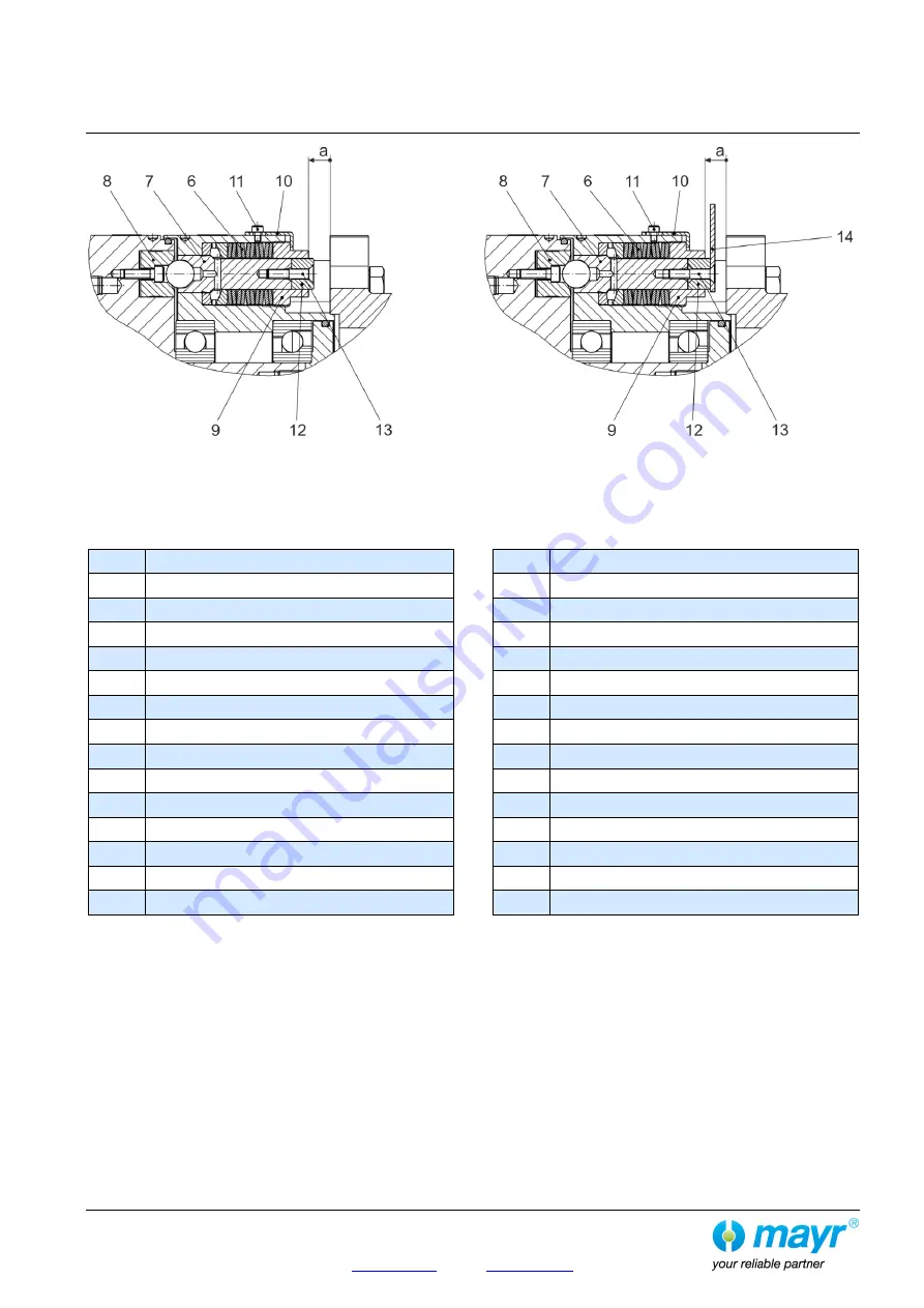
Fig. 3:
Fig. 4:
Detail overload element (Item 6),
Type 404_._0400
Detail overload element (Item 6), Type 404_._1400
(Design without switching disk (14))
(Design with switching disk (14))
Parts List
(Only use
mayr
®
original parts)
Item
Name
Item
Name
1
Hub
15
Control flag
2)
2
Set screw
16
Cap screw
3
Element flange
17
Cone lubricating nipple (elements greasing)
4
Hexagon head screw
18
Cone lubricating nipple (bearing greasing)
5
Pressure flange
19
Eyebolt
6
Overload element
20
Cam ring
7
Bolt
21
Cap screw
8
Thrust piece
22
Locking washer
9
Adjusting nut
23
Flexible intermediate ring
10
Lock washer
24
Claw ring
11
Cap screw
25
Set screw
12
Distance bushing
26
Flange hub
13
Countersunk screw
27
Centring ring
14
Switching disk
1)
(Type 404_._1400)
28
Set screw
1)
Item 14 for overload recognition using a limit switch
2)
Item 15 for overload recognition using a speed monitoring device


