background image

Installation and Operational Instructions for


ROBA

®

-brake-checker DC Type 058.600.2 

(B.0586002.EN)

your reliable partner

28/06/2019 TF/GF

Page 2 of 10

Chr. Mayr GmbH + Co. KG
Eichenstraße 1, D-87665 Mauerstetten, Germany
Tel.: +49 8341 804-0, Fax: +49 8341 804-421

www.mayr.com

, E-Mail: 

info@mayr.com

22

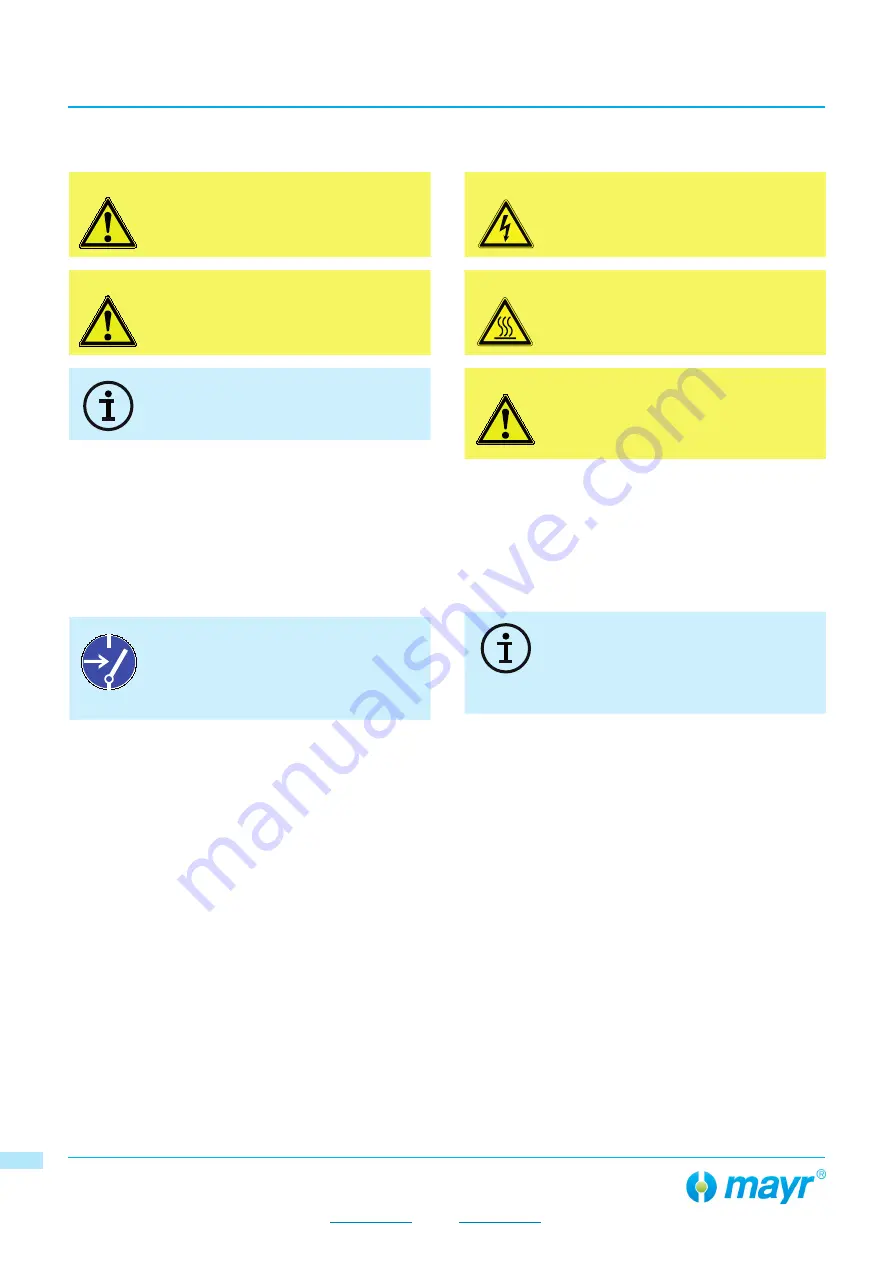
Safety and Guideline Signs

DANGER

Immediate and impending danger, which 
can lead to severe physical injuries or to 
death.

CAUTION

Danger of injury to personnel and damage 
to machines.

Guidelines on important points

General Safety Guidelines

DANGER

Danger of death! Do not touch voltage-
carrying lines and components.

DANGER

Danger of burns when touching hot 
surfaces.

CAUTION

•  Danger of device failures caused by 

short-circuits and earth short-circuits at 

the terminals

•  Electronic devices cannot be guaranteed 

fail-safe.

During the risk assessment required when designing the 
machine or system, the dangers involved must be evaluated 
and removed by taking appropriate protective measures. 
To prevent injury or damage, only professionals and 
specialists are allowed to work on the devices. They must 
be familiar with the dimensioning, transport, installation, 
initial operation, maintenance and disposal according to the 
relevant standards and regulations.

Before product installation and initial opera-
tion, please read the Installation and Opera-
tional Instructions carefully and observe the 
Safety Regulations. Incorrect operation can 
cause injury or damage.

General Safety Guidelines

Only carry out installation, maintenance and 
repairs in a de-energised, disengaged 
state and secure the system against inad-
vertent switch-on.

22

Summary of Contents for ROBA 058.600.2

Page 1: ...ectromagnetic fields Guidelines on the Machinery Directive 2006 42 EC The product is a component for installation into machines according to the Machinery Directive 2006 42 EC The product can fulfil the specifications for safety related applications in coordination with other elements The type and scope of the required measures result from the machine risk analysis The product then becomes a machi...

Page 2: ...t circuits and earth short circuits at the terminals Electronic devices cannot be guaranteed fail safe During the risk assessment required when designing the machine or system the dangers involved must be evaluated and removed by taking appropriate protective measures To prevent injury or damage only professionals and specialists are allowed to work on the devices They must be familiar with the di...

Page 3: ...cker DC monitoring module is inten ded for use with an input voltage of up to 50 VDC The monitoring module monitors the movement of the armature disk and emits the determined switching condition via con trol terminal signal output Critical conditions line breakages wear excess temperatu re can be recognised and the respective signal can be emit ted via control terminal error output The movement de...

Page 4: ...alue due to oiling of the brake lining Possible causes for the warning Increasing wear Rising coil temperature Falling supply voltage Line voltage drop on feed lines to the brake Technical data Supply voltage control terminal SELV PELV Ripple content 5 UI VDC 24 7 32 Coil current max Imax A 15 at 45 C IRMS A 10 at 60 C IRMS A 8 at 70 C IRMS A 8 Device fuses 1 2 IO fast acting or circuit breaker 10...

Page 5: ...erstetten Germany Tel 49 8341 804 0 Fax 49 8341 804 421 www mayr com E Mail info mayr com 5 5 Wiring Example Electrical connection Brake ROBA brake checker DC Type 058 600 2 Control terminal 11 Reset Input RST 12 Do not assign IN 13 Error output max 100 mA ERR 14 Signal output max 100 mA OUT 15 Supply voltage 0 VDC GND 16 Supply voltage 24 VDC 24 V Power terminal 1 Supply voltage 6 50 VDC 2 Output...

Page 6: ...time tC 400 ms Calibration time tR 600 ms Reset time tP 10 100 ms Pulse time must be less than 100 ms greater than 10 ms Output t t UOUT UI ERR RST tR tB tC tP OUT 14 0 VDC low Brake is not energised movement of the armature disk for closing the brake 0 99 UI high Brake energised movement of the armature disk for opening the brake ERR 13 0 99 UI high no errors 0 VDC low Brake does not open or clos...

Page 7: ...ity Nominal Values Reset Fast switch off Inching Mode During inching mode fast sequence of switching on and off no reliable detection is possible After the end of inching mode restart the monitoring function De energise the brake Switch on energise the brake again Repeated switch on energisation before the brake is closed generates a fault when the maximum current is reached Start process During e...

Page 8: ...s as short as possible do not form rings or loops with the cables Mount good earth connections onto the metal body of the brake Lay control cables total length 30 m separately from power cables or from strongly pulsating supply cables Continuous drop out recognition The continuous drop out recognition can detect the follow ing situation and signal it via the outputs Brake is energised Undesired mo...

Page 9: ... 0586002 EN your reliable partner 28 06 2019 TF GF Page 9 of 10 Chr Mayr GmbH Co KG Eichenstraße 1 D 87665 Mauerstetten Germany Tel 49 8341 804 0 Fax 49 8341 804 421 www mayr com E Mail info mayr com 9 9 Functional sequence diagram Slow switch off Fast switch off Warning Error Output current Output volt age Signal Output Error Output 9 9 ...

Page 10: ...ode No 160214 mixed materials or components under Code No 160216 Code No acc 200 532 EC or can be disposed of by a certified disposal firm Malfunctions Breakdowns Malfunction Possible Causes Measures Brake does not release No supply voltage available Check voltage on input terminal Brake line interrupted Check brake supply line check passage Line voltage drop on long line Check the brake voltage N...

Reviews: