Installation- and Operational Instructions
for ROBA-stop
®
-M Brakes
Type 891. _ _ _ . _ Sizes 2 – 500
(B.8.1.GB)
16/11/2005 TK/KE/RJ
Chr. Mayr GmbH + Co. KG
Tel.: 08341 / 804-0
Eichenstraße 1
Fax: 08341 / 804-421
D-87665 Mauerstetten
http://www.mayr.de
Page 10 of 17
Germany
eMail:
info@mayr.de
6. Braking Torque Adjustment
ROBA-stop
®
-M brakes are adjusted by the manufacturer to the
required braking torque, which should be stated on ordering.
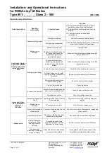
Different braking torque adjustments can be made using different
spring parts (6) in the coil carrier (2), (see Table 7).
The required thrust spring part (6) is to be adjusted to the requested
braking torque and installed at the manufacturing site (see Table 7).
Should user-installation of the part be unavoidable, please order the
required thrust spring set (6) with exact size and braking torque
adjustment.
Exchanging the thrust springs (6):
(Warning: the brake must be load-free)
To change the thrust springs (6), the brake must be unscrewed from
the motor bearing shield or from the machine wall.
6.1. Remove the fixing screws (8).
6.2. Unscrew the shoulder screws (10) from the coil carrier (2) and
remove the armature disc (3).
Warning: The thrust springs (6) press against the armature
disc (3). To remove the shoulder screws (10), the armature
disc (3) must be pressed against the coil carrier (2) to avoid a
sudden release of the thrust springs (6).
Please observe the armature disc (3) installation point, and
make sure that the thrust springs (6) don’t fall out.
Warning: Danger of injury
6.3. Replace the thrust springs (6).
Warning: Insert the new thrust-spring set (6) in symmetrical
order.
6.4. Lay the armature disc (3) onto the coil carrier (2) or the thrust
springs (6), (observe the installation point: use fixing screws as
centering aid for sizes 2 – 60 if necessary).
6.5. Press the armature disc (3) against the spring force and screw
on the shoulder screws (10) with the tightening torque (see
Table 3).
6.6. Screw the brake onto the motor bearing shield or the machine
wall using the fixing screws (8).
(Please observe the tightening torque, see Table 2).
7. Brake inspection
(Before using the brake)
-
Braking torque inspection:
Compare the requested braking torque with the braking torque
stated on the Type tag (26).
-
Release inspection:
This is done by energising the brake or by manually operating the
hand release (dependent on type).
The braking torque is not reached until the run-in procedure has
been completed.
The braking torque (switching torque) is the torque effect in the
shaft line when the brake slips at a sliding speed of 1 m/s in
relation to the middle friction radius (according to DIN VDE
0580/07.2000).
8. Installation of the hand release
(see Figs. 1 and 5)
For Type 891._ _ _.1, the installation of the hand release is only
then possible, if the request for hand release is stated on the brake
order form (completely closed coil carrier (2)).
The brake must be dismantled and de-energised to
install the hand release.
Installation Procedures:
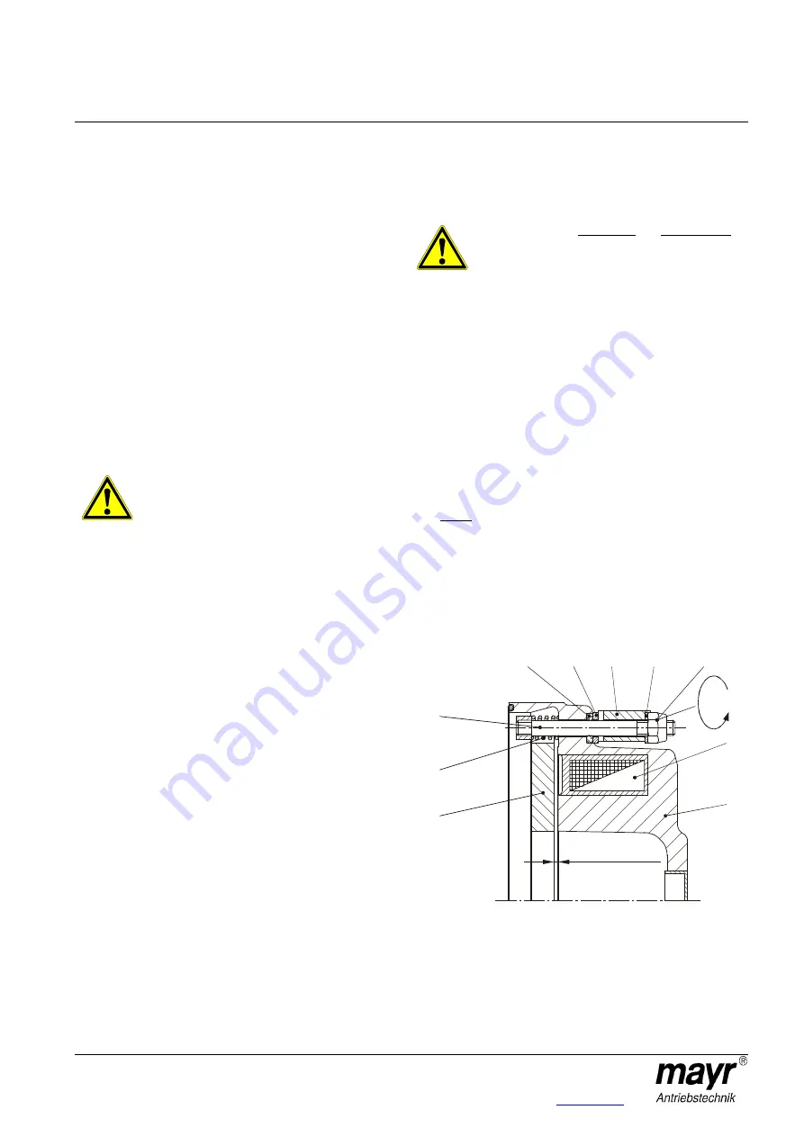
8.1. Place the thrust-springs (18) onto the threaded bolts (17). The
threaded bolts (17) are manufactured with a key as a tension
element and, up to size M60, are secured with glue. This
connection must not be loosened / removed.
8.2. Push the threaded bolts (17) with the thrust-springs (18) from
inside (facing the magnetic coil (7)) into the hand release bores
in the coil carrier (2).
8.3. Push the O-rings (21) (only when the hand release is sealed,
Type 891._ _ _.1) over the threaded bolts (17) and insert them
into the coil carrier (2) recesses. Avoid crushing the O-rings
(21).
8.4. Push the intermediate plates (22) (only with sealed hand
release, Type 891._ _ _.) over the threaded bolts (17).
8.5. Put the switch bracket (16) in place, put the washers (20) on it
and lightly screw on the self-locking hexagon nuts (19).
8.6. Tighten both hexagon nuts (19) until the armature disc (3) lies
evenly on the coil carrier (2).
8.7. Loosen both hexagon nuts (19) by “y“ turns (see Table 2),
thereby creating an air gap between the armature disc (3) and
the coil carrier (2). This gives you the inspection dimension “x“.
Warning: An unequal alignment dimension on the hand
release can cause the brake to malfunction.
8.8. After installing the release cover, screw and tighten the hand
release bar (15) in the switch bracket (16).
The hand release bar (15) must be protected from loosening
with a screw-securing product e.g. Loctite 243.
Fig. 5
Warning:
The inspection dimension "x" (Fig. 5) serves purely for the
hand release adjustment in dismantled condition.
21
22
16
20
19
Y
7
2
17
18
3
Inspection
dimension “x”


