background image

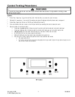
Component Testing Procedures 


!

WARNING


To avoid risk of electrical shock, personal injury or death; disconnect power to range before servicing, unless  
testing requires power. 


November 2005 

16026688 

© 2005 Maytag Services 


Illustration Component 

Test 

Procedure 

Results 


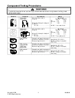
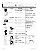
Infinite switch 
(MER5752BA*) 


Connect volt-ohms meter to  
H1 and H2. 
 
 
Measure the following for voltages at 
LO, MED, HI: 
 

H1 to H2 ........................................

Approximate 


Time On 

Time Off 

LO 5% 


95% 

MED (4-5) 

35% 


65% 

HI 100% 


0% 

 
240 VAC.  If not, replace switch. 


Infinite switch  
(MER5752BA*) 


Connect volt-ohms meter to  
H1 and H2. 
 
 
Measure the following for voltages at 
LO, MED, HI: 
 

H1 to H2 ........................................

Approximate 


Time On 

Time Off 

LO 6% 


94% 

MED (4-5) 

40% 


60% 

HI 100% 


0% 

 
240 VAC.  If not, replace switch. 


Ribbon element, 
2500W 

Disconnect wire leads to element and 
measure cold resistance of terminals ...
Measure voltage at element..................

 
Approximately 21.3 to 23.5 

240 VAC. If voltage is not present, 
check wiring. 


Ribbon element, 
ceramas, 2700W 
(MER5752BA*, 
MERH752BA*) 

Disconnect wire leads to element and 
measure cold resistance of terminals ...
Measure voltage at element..................

 
Approximately 19.4 to 22 

240 VAC. If voltage is not present, 
check wiring. 


Ribbon element, 
1200W 

Disconnect wire leads to element and 
measure cold resistance of terminals ...
Measure voltage at element..................

 
Approximately 44.3 to 48.9 

240 VAC. If voltage is not present, 
check wiring. 
Summary of Contents for AER5712BA Series

Page 1: ...element dual 2 500 2 500 2 500 2 500 2 500 Ribbon element 6 inch 1 200 1 200 1 200 1 200 1 200 Ribbon element ceramas N A N A 2 700 2 700 N A Oven Wattage 240 V 208 V Bake 4 pass 2 600 1950 2 600 1950...

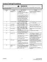
Page 2: ...20 6 to 22 6 240 VAC see wiring diagram for terminal identification If voltage is not present at bake element check wiring Broil element Disconnect wire leads to element and measure resistance of ter...

Page 3: ...ollowing for voltages at LO MED HI H1 to H2 Approximate Time On Time Off LO 6 94 MED 4 5 40 60 HI 100 0 240 VAC If not replace switch Ribbon element 2500W Disconnect wire leads to element and measure...

Page 4: ...play M1 Factory default Press and hold Cancel and Keep Warm pads for 3 to 5 seconds until beep sounds Allows the clock to be reset to factory settings M1 12 hour off Control automatically cancels cook...

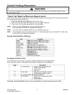
Page 5: ...test the Quick Test mode will be disabled Display will indicate the following Key Operation Bake Bake relay activated DLB relay activated Broil Broil relay activated DLB relay activated Keep Warm DLB...

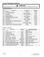
Page 6: ...state unknown neither locked or unlocked Always 1 minute Diagnostic Code Handling Code Measurable Displayed Action Taken By Control 1c1c Keypress Nothing Disables audible for key depression Disables k...

Page 7: ...ools 5 Special conditions for latch faults 9dxx A known good unlock position is defined as when the unlock switch reads closed and lock switch reads open A known good lock position is defined as when...

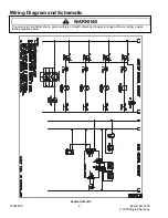
Page 8: ...nd Schematic WARNING To avoid risk of electrical shock personal injury or death disconnect power to range before servicing unless testing requires power 16026688 8 November 2005 2005 Maytag Services C...

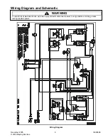
Page 9: ...and Schematic WARNING To avoid risk of electrical shock personal injury or death disconnect power to range before servicing unless testing requires power November 2005 9 16026688 2005 Maytag Services...

Reviews: