background image

42

MAYTAG GAS WATER HEATERS

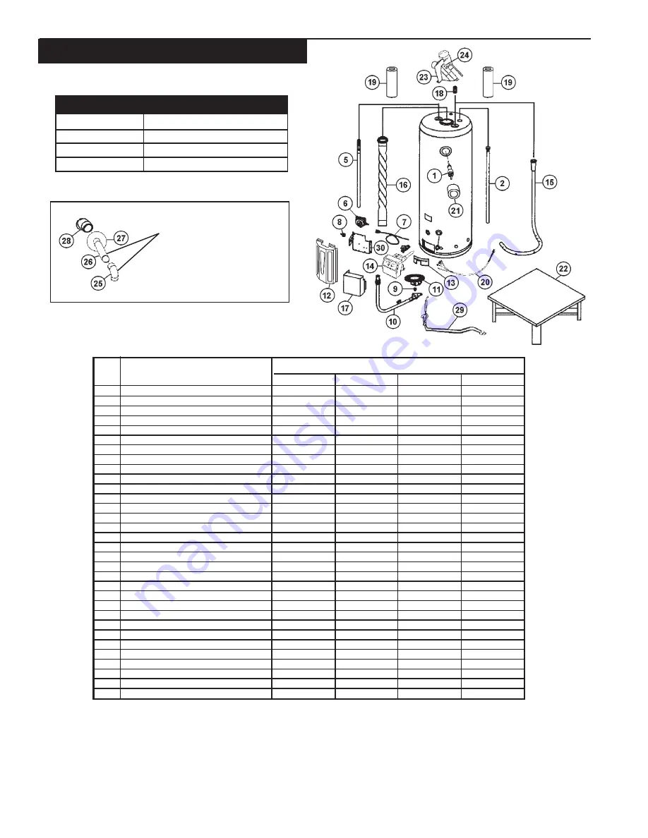
REPAIR PARTS LIST

Now that you have purchased this gas water heater, should a need
ever exist for repair parts or service, simply 

call Maytag Customer

Service at 1-800-788-8899 for an authorized servicer

. Be sure to

provide all pertinent facts when you call or visit.

THIS IS A REPAIR PARTS LIST, NOT A PACKING LIST.

The model number of this gas water heater will be found on the model
rating plate located near the gas control valve.

When ordering repair parts, always give the following information:

Model number

Serial Number

Part Description

Part Number

MODEL NO’S

HRN11250P

50  Gallon Natural Gas

HRN31250P

50  Gallon Natural Gas

HRP11250P

50 Gallon Propane Gas (L.P.)

HRP31250P

50 Gallon Propane Gas (L.P.)

 * Not Shown.


Key

        Model Numbers

 No.

Part  Description

HRN11250P

HRN31250P

HRP11250P

HRP31250P

1

Temperature-Pressure Relief Valve

66001700

66001700

66001700

66001700

2

Primary Anode Rod

66001020

66001020

66001020

66001020

3

Drain Valve

66001015

66001015

66001015

66001015

*4

Drain Valve Washer 

(17/32” x 13/64” x 1/8” thick)

66001021

66001021

66001021

66001021

5

Secondary Anode Rod w/Heat traps

66001898

66001898

66001898

66001898

6

Pressure Switch

66001368

66001368

66001368

66001368

7

Power Cord

66001372

66001372

66001372

66001372

8

On/Off Switch

66001247

66001247

66001247

66001247

9

Burner Orifice (Drill Size)

66001538

66001638

66001540

66001515

10

Manifold

66001659

66001659

66001659

66001659

11

Burner

66001027

66001027

66001027

66001027

12

Outer Door

66001190

66001190

66001190

66001190

13

Inner Door

66001029

66001029

66001029

66001029

14

Gas Control Valve (Natural)

66001527

66001527

- - - - - - - -

- - - - - - - -

14

Gas Control Valve (Propane{L.P.])

- - - - - - - -

- - - - - - - -

66001528

66001528

15

Dip Tube

66001052

66001052

66001052

66001052

16

Flue Baffle

66001399

66001399

66001399

66001399

17

Junction Box Cover

66001899

66001899

66001899

66001899

18

Inlet Nipple w/Heat Traps

66001707

66001707

66001707

66001707

19

Pipe Insulation (2 ea.)

66001755

66001755

66001755

66001755

20

Wiring Harness

66001526

66001526

66001526

66001526

21

T & P Insulation

66001709

66001709

66001709

66001709

22

Water Heater Stand

66001243

66001243

66001243

66001243

23

Blower/ Draft Hood Ass’y

66001366

66001366

66001366

66001366

24

Venting Switch

66001367

66001367

66001367

66001367

25

3” or 2” Schedule 40 90

o

 Elbow

- - - - - - - - -

- - - - - - - -

- - - - - - - -

- - - - - - - -

26

3” or 2” Schedule 40 Vent Pipe

- - - - - - - -

- - - - - - - -

- - - - - - - -

- - - - - - - -

27

Wall Collar

66001262

66001262

66001262

66001262

28

3” PVC Vent Terminal

66001255

66001255

66001255

66001255

29

Hot Surface Ignition Ass’y

66001525

66001525

66001525

66001525

30

Mounting Bracket

66001896

66001896

66001896

66001896

*31

Manual

66001897

66001897

66001897

66001897

PCV, ABS OR CPVC ITEMS
FOR ALL MODELS SUPPLIED
LOCALLY

Summary of Contents for HRN11240P

Page 1: ...BLE FOR SPACE HEATING NOT FOR USE IN MANUFACTURED MOBILE HOMES Model Numbers For Your Safety AN ODORANT IS ADDED TO THE GAS USED BY THIS WATER HEATER POWER VENT GAS WATER HEATER USER S GUIDE Series Twelve HRN11240P HRN31240P HRP11240P HRP31240P HRN11250P HRN31250P HRP11250P HRP31250P HRN11275P HRN31275P HRP11275P HRP31275P ...

Page 2: ...d gas supply including a thorough understanding of the requirements of the National Fuel Gas Code as it relates to the installation of gas fired water heaters The Service Center also has a thorough understanding of this instruction manual and is able to perform repairs strictly in accordance with the service guidelines provided by the manufacturer Gas Supplier The natural gas or propane utility or...

Page 3: ...3 SAFETY PRECAUTIONS ...

Page 4: ... 17 18 Wiring Diagram 18 Venting 19 25 Gas Piping 26 Sediment Trap 27 OPERATING INSTRUCTIONS 28 31 Operating 29 Temperature Regulation 29 31 Lighting Operating Label 30 SERVICEAND MAINTENANCE 32 34 Tank Sediment Cleaning 32 Venting System Inspection 32 Burner Inspection 32 Burner Cleaning 32 L P Gas Control Valve Burner Assembly Replacement Information 33 Housekeeping 33 Anode Rod Inspection 33 Dr...

Page 5: ...tions for the installation operation and maintenance of the gas fired water heater It also contains warnings through out the manual that you must read and be aware of All warnings and all instructions are essential to the proper operation of the water heater and your safety Since we cannot put everything on the first few pages READ THE ENTIRE MANUALBEFOREATTEMPTING TOINSTALLOROPERATETHEWATERHEATER...

Page 6: ...ESSAND 28 711 mm DIAMETER PART NO 66001012 FOR WATER HEATERS HAVING A DIAMETER 26 660 mm OR LESS Tools You may or may not need all these tools depending on your type of installation These tools can be purchased at your local hardware store Pipe Wrenches 2 14 356 mm Screwdriver Tin Snips 6 1 82 m Tape or Folding Ruler Garden Hose Drill Pipe Dope or Teflon Tape Additional Tools Needed When Sweat Sol...

Page 7: ...the vent pipe can be lifted off after any screw or other attached devices are removed Dispose of the draft hood The new water heater has the draft hood which must be used for proper operation 6 If you have copper piping to the water heater the two copper water pipes can be cut with a hacksaw approximately four inches away from where they connect to the water heater This will avoid cutting off pipe...

Page 8: ...IGURE7 I Drip Leg Sediment Trap J Inner Door K Outer door L Union M Inlet Water Shut off Valve N Cold Water Inlet O Inlet Dip Tube P Temperature Pressure Relief Valve Q Rating Plate R Flue Baffle S Thermostat T Drain Valve U Pilot and Main Burner V Flue W Drain Pan U PILOT MAIN BURNER S THERMOSTAT ALL PIPING MATERIALS TO BE SUPPLIED BY CUSTOMERS CLOSED WATER SYSTEMSARE THOSE WITH BACK FLOW PREVENT...

Page 9: ...perature setting that satisfies your hot water needs a means such as a Mixing Valve shall be used at the hot water taps used by these people or at the water heater Mixing valves are available at plumbing supply or hardware stores See Figure 8 Valves for reducing point of use temperature by mixing cold and hot water are also available Consult Maytag Customer Service 1 800 788 8899 Follow mixing val...

Page 10: ...tem It cannot be connected to an existing vent pipe or chimney It must be terminated to the outdoors Failure to properly install the venting system can result in asphyxiation a fire or explosion and can cause DEATH SERIOUS BODILY INJURY OR PROPERTY DAMAGE The water heater comes equipped with a 7 foot power cord which can be used to connect to a 110 120 volt power source if 1 local codes allow and ...

Page 11: ...east 3 inches 76 2 mm in any direction or if the appliance is installed in an alcove or closet the entire floor must be covered by the panel Failure to heed this warning may result in a fire hazard Minimum clearances between the water heater and combustible construction are 0 inch at the sides and rear 6 inches 152 mm at the front and 0 inches from the vent pipe Clearance from the top of the jacke...

Page 12: ...er see Figure 15 FIGURE15 Vent termination must not be within 4 feet of any items such as gas meters gas valves or other gas regulating equipment The venting system must be installed in a manner which allows inspection of the installation of the venting pipes and joints as well as periodic inspection after installation as required by ANSI Standards Vent termination must not be within 4 feet of any...

Page 13: ...ating of all appliances installed in that space Rooms communicating directly with the space in which the appliances are installed through openings not furnished with doors are considered a part of the unconfined space In unconfined spaces in buildings infiltration may be adequate to provide air for combustion ventilation and dilution of flue gases However in buildings of tight construction for exa...

Page 14: ...a consideration shall be given to the blocking effect of louvers grilles or screens protecting openings Screens used shall not be smaller than 1 4 inch 6 4 mm mesh If the free area through a design of louver or grille is known it should be used in calculating the size opening required to provide the free area specified If the design and free area is not known it may be assumed that wood louvers wi...

Page 15: ...t the insulation does not interfere with the lever of the T P valve addition to using the lowest possible temperature setting that satisfies your hot water needs a means such as a mixing valve shall be used at the hot water taps used by these people or at the water heater Mixing valves are available at plumbing supply or hardware stores see Figure 8 on page 9 and Figure 21 below Valves for reducin...

Page 16: ...above or at any distance below the structural floor Be certain that no contact is made with any live electrical part The discharge opening must not be blocked or reduced in size under any circumstances Excessive length over 30 feet 9 14 m or use of more than four elbows can cause restriction and reduce the discharge capacity of the valve see Figure 24 No valve or other obstruction is to be placed ...

Page 17: ...use To insure complete filling of the tank allow air to exit by opening the nearest hot water faucet Allow water to run until a constant flow is obtained This will let air out of the water heater and the piping Check all water piping and connections for leaks Repair as needed Wiring USEWITHPOWERCORD The water heater comes equipped with a 7 foot power cord which can be used to connect to a 110 120 ...

Page 18: ...r junction box for the conduit connection Use wire nuts and connect the power supply wiring to the wires inside the water heater s junction box The water heater must be electrically grounded by the installer The unit will not operate unless it is properly grounded A green ground screw has been provided on the water heater s junction box Connect ground wire to this location For complete grounding d...

Page 19: ...ning solvents refrigerator and air conditioner refrigerants swimming pool chemicals calcium and sodium chloride waxes bleach and process chemicals are typical compounds which are potentially corrosive Horizontal runs must be securely supported at 3 1 2 foot intervals and vertical runs supported at 5 foot intervals FIGURE29 VENTINGTHROUGHANOUTSIDEWALL 75 GALLON 70 000AND 75 000 BTU HR MODELS ONLY S...

Page 20: ...0 45o vent cap with wire screen is supplied with the water heater A 3 PVC ABS or CPVC Schedule 40 90o street ell used to connect the vent pipe to the water heater when the vent pipe is to be turned horizontally directly off the blower supplied locally 3 PVC ABS or CPVC Schedule 40 pipe must be supplied locally FIGURE32 The water heater requires its own separate venting system 3 PVC ABS or CPVC Sch...

Page 21: ...imney It must terminate horizontally to the outdoors NOTE See pages 24 and 25 for vertical venting through the roof VENTINGSYSTEMEXAMPLEINSTALLATIONS FORALLMODELS The vent piping cannot under any circumstances be run down hill FIGURE34 The vent piping may be installed as follows Horizontal runs require a minimum 1 8 rise per five feet FIGURE35 FIGURE36 FIGURE37 75 GALLON 70 000 AND 75 000 BTU HR M...

Page 22: ...1 110 2 105 3 100 4 95 5 90 6 ALL40 AND 50 GALLON 40 000 BTH HR MODELS ONLY OPTIONAL 2 VENT PIPING 2 DIA VENT NUMBEROF MAX LENGTH FT 90o ELBOWS 50 1 45 2 40 3 35 4 30 5 25 6 Two 45o elbows are equivalent to one 90o elbow One 90o elbow equals 5 feet of equivalent vent length FIGURE40 Minimum vent length for all 40 000 BTU HR input models is 4 feet and 16 inches for all other models VENTING THROUGHA...

Page 23: ...case of eye and skin contact immediately flush with plenty of water for 15 minutes and seek medical attention if irritation persists KEEP OUT AND REACH OF CHILDREN All primers cleaners and cements must meet all local codes and applicable standards of the American Society for Testing Materials Standards Before using primers cleaners and cements stir or shake making sure contents of liquid Do not us...

Page 24: ...pipe must be attached to the blower using 3 sheet metal screws FIGURE45 If the optional 2 vent piping is to be used 40 000 BTU HR models only the 2 street elbow 3 to 2 reducer and 3 minimum section of 3 PVC ABS or CPVC pipe must be supplied locally The 3 minimum section of 3 PVC ABS or CPVC pipe must be attached to the blower using 3 sheet metal screws If the optional 4 vent piping is to be used 7...

Page 25: ...locally FIGURE47 The water heater requires its own separate venting system It cannot be connected to existing vent piping or chimney It must terminate vertically to the outdoors Typical installation s in next column Refer to Cementing PVC ABS or CPVC pipe and fittings on page 23 and Connecting Vent to Blower on page 24 FIGURE48 The total vertical and horizontal vent runs cannot exceed the maximum ...

Page 26: ...m inlet gas pressure shown on the rating plate is that which will permit firing at the rated input If a standard model is installed above 3 300 feet 1 006 m or a high altitude model is installed above 5 500 feet 1 676 m the input rating should be reduced at the rate of 4 percent for each 1 000 feet 305 m above sea level which requires replacement of the burner orifice in accordance with National F...

Page 27: ...tion of the National Fuel Gas Code ANSI Z223 1 NFPA 54 A sediment trap shall be installed as close to the inlet of the water heater as practical at the time of water heater installation The sediment trap shall be either a tee fitting with a capped nipple in the bottom outlet or other device recognized as an effective sediment trap If a tee fitting is used it shall be installed in conformance with ...

Page 28: ...the ON position for the electrical control system to operate allowing the gas portion to operate ignite burner 3 The venting manual reset switch must be in the closed position See Venting Manual Reset Switch in the Troubleshooting section 4 There is a non resettable hi limit switch in the thermostat which must be good closed for the thermostat to be operated See High Temperature Limit Switch in th...

Page 29: ...lower 5 Cycle is completed CONTROLSEQUENCE HOTSURFACEDIRECTIGNITION Pre purge 5 sec HSI Warm Up 20 sec Ignition Activation Period 4 sec Flame Recognition Period 1 sec Ignition Trial 4 sec Interpurge 5 sec Post purge 5 sec Retries 2 Reset from lockout 1 hr Flame Sensing Nominal HSI Off Run Mode 4 0 µ VDC Temperature Regulation Short repeated heating cycles caused by small hot water uses can cause t...

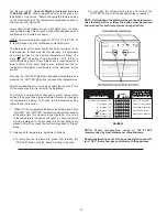
Page 30: ...mperature settings the control has a tamper resistant feature for changing the temperature setting To change the temperature setting follow these instructions 1 Wake Up the temperature indicators by holding down both COOLER and HOTTER temperature adjustment buttons at the same time for one second see Figure 49 One or two of the temperature indicators will light up These indicators will only remain...

Page 31: ...The appliance is equipped with a device which automatically lights the burner DONOTTRYTOLIGHTTHEBURNERBYHAND 6 Wait five 5 minutes to clear out any gas If you then smell gas STOP Follow B in the safety information above on this label If you don t smell gas go to next step 7 Turn on all electrical power to the appliance 8 Set the ON OFF switch on the control box to the ON position 9 Set the thermos...

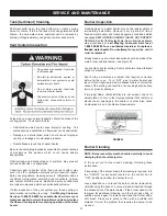
Page 32: ... operation of the water heater Burner Inspection Flood damage to a water heater may not be readily visible or immediately detectable However over a period of time a flooded water heater will create dangerous conditions which can cause DEATH SERIOUS BODILY INJURY OR PROPERTY DAMAGE Contact the Maytag dealer from whom the appliance was purchased or call Maytag Customer Service at 1 800 788 8899 for ...

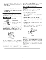
Page 33: ...o protect the tank from corrosion Most hot water tanks are equipped with an anode rod The submerged rod sacrifices itself to protect the tank Instead of corroding the tank water ions attack and eat away the anode rod This does not affect the water s taste or color The rod must be maintained to keep the tank in operating condition Anode deterioration depends on water conductivity not necessarily wa...

Page 34: ...alve on the appliance weeps or discharges periodically this may be due to thermal expansion You may have a check valve installed in the water line or a water meter with a check valve Consult Maytag Customer Service at 1 800 788 8899 for further information Do not plug the temperature pressure relief valve Drain Valve Washer Replacement See Figure 56 NOTE For ordering replacement washers refer to t...

Page 35: ...sed As water is heated it expands thermal expansion and closed systems do not allow for the expansion of heated water The water within the water heater tank expands as it is heated and increases the pressure of the water system If the relieving point of water heater s temperature pressure relief valve is reached the valve will relief the excess pressure The temperature pressure relief valve is not...

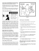
Page 36: ...and thus avoid repeated thermostat replacement Lower the temperature adjustment setting on new control Call Maytag Customer Service at 1 800 788 8899 for an authorized servicer Should overheating occur or the gas supply fail to shut off turn OFF the manual gas control valve to the appliance Venting Manual Reset Switch There is a venting manual reset switch located on the draft hood If the venting ...

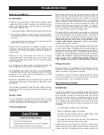
Page 37: ...ure pressure relief valve may be leaking at the tank fitting F Water from a drain valve may be due to the valve being slightly opened G The drain valve may be leaking at the tank fitting H Combustion products contain water vapor which can condense on the cooler surfaces of the tank Droplets form and drip onto the burner or run on the floor This is common at the time of start up after installation ...

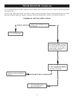
Page 38: ...s operation resulting in DEATH SERIOUS BODILY INJURY OR PROPERTY DAMAGE TROUBLESHOOTING Continued THERMOSTAT AND GAS SUPPLY CHECK NO Is gas being supplied to the thermostat YES Is thermostat calling for heat Run HOT water from heater and set adjustment button higher Check using a manometer at thermostat pressure tap YES Is there a minimum gas pressure 4 W C for natural gas or 10 W C for propane L ...

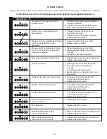
Page 39: ...ltage to the water heater 4 Electric polarity to unit is incorrect test and correct Problem in the gas valve driver circuit 1 Turn power to the water heater off for 10 seconds and then back on 2 Replace gas control valve Problem with the internal circuit 1 Turn power to the water heater off for 10 seconds and then back on 2 Replace gas control valve Problem with the internal circuit 1 Turn power t...

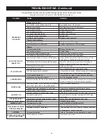
Page 40: ... intake exhaust venting and air openings in bottom base pan for obstructions or blockage C Not enough dilution air Check dilution air intake for obstructions or blockage A Water on the floor under heater See Condensation section B Water dripping from the blower assembly Provide drip TEE to catch condensation from horizontal section of exhaust vent close to blower assembly Improperly sealed hot or ...

Page 41: ...ord 66001372 66001372 66001372 66001372 8 On Off Switch 66001247 66001247 66001247 66001247 9 Burner Orifice Drill Size 66001538 66001538 66001538 66001538 10 Manifold 66001530 66001530 66001533 66001533 11 Burner 66001027 66001027 66001027 66001027 12 Outer Door 66001190 66001190 66001190 66001190 13 Inner Door 66001029 66001029 66001029 66001029 14 Gas Control Valve Natural 66001527 66001527 14 ...

Page 42: ...ord 66001372 66001372 66001372 66001372 8 On Off Switch 66001247 66001247 66001247 66001247 9 Burner Orifice Drill Size 66001538 66001638 66001540 66001515 10 Manifold 66001659 66001659 66001659 66001659 11 Burner 66001027 66001027 66001027 66001027 12 Outer Door 66001190 66001190 66001190 66001190 13 Inner Door 66001029 66001029 66001029 66001029 14 Gas Control Valve Natural 66001527 66001527 14 ...

Page 43: ...rill Size 66001900 66001901 66001902 66001903 9 Manifold 66001532 66001532 66001532 66001532 10 Burner 66001221 66001221 66001221 66001221 11 Outer Door 66001190 66001190 66001190 66001190 12 Inner Door 66001146 66001146 66001146 66001146 13 Gas Control Valve Natural 66001657 66001657 13 Gas Control Valve Propane L P 66001658 66001658 14 Dip Tube 66001030 66001030 66001030 66001030 15 Flue Baffle ...

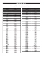
Page 44: ...01366 9003081 66001367 9003082 66001368 9003089 66001369 9003090 66001372 9003095 66001399 9003083 66001400 9003156 66001401 9003153 66001402 9003152 66001403 9003154 66001404 9003157 66001405 9000736 66001515 9003453 66001524 9003626 66001525 9003627 66001526 9003628 66001527 9003629 66001528 9003630 66001530 9003685 66001532 9003687 66001533 9003688 66001538 9003493 66001540 9003495 66001617 900...

Page 45: ...45 NOTES ...

Page 46: ...46 NOTES ...

Page 47: ...47 NOTES ...

Page 48: ...ginal retail purchase if a leak occurs in the tank a new water heater of the closest capacity and quality then available will be replaced free of charge for the water heater with the owner paying all other costs including labor mileage and transportation If the water heater is subjected to commercial institutional industrial or non residential use the above warranty coverage for the tanks that are...

Reviews: