7. BAROMETRIC DAMPER CONTROL.
The barometric damper control, also known as a draft
regulator, is used on conventional chimney venting only.
This control automatically maintains a constant negative
pressure in the furnace to obtain maximum efficiency. It
ensures that proper pressures are not exceeded. If the
chimney does not develop sufficient draft, the draft
control cannot function properly. The draft regulator,
when installed should be in the same room or enclosure
as the furnace and should not interfere with the
combustion air supplied to the burner. The control should
also be located near the furnace flue outlet and installed
according to the instructions supplied with the regulator.
The flue outlet pressure (measured between the furnace
and draft regulator, or the oil burner mounting plate over-
fired draft access port. fig. 2) should be set to -0.02 in.
w.c.
9.
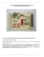
FAN TIMER BOARD AND LIMIT CONTROL
(FIG. 4) (page 19)
The
United Technologies 1168-1 ECM
(POF1HD140AVFA and POF1HD091AVFA)
tap board
has an adjustable fan on/off delay that must be adjusted
in accordance with the furnace input rating (nozzle size).
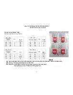
Refer to Table A-10 (pg 15) for ECM blower set-up.
10. ELECTRICAL CONNECTIONS
The furnace is listed by the Canadian Standards
Association under the NRTL (North American) Standard.
It is factory wired and requires minimal field wiring. All
field wiring should conform to CAN/CSA C22.1 Canadian
Electrical Code, Part 1, and by local codes, where they
prevail. In the United States, the wiring must be in
accordance with the National Fire Protection Association
NFPA-70, National Electrical Code, and with local codes
and regulations.
The furnace should be wired to a separate and dedicated
circuit in the main electrical panel; however, accessory
equipment such as electronic air cleaners and
humidifiers may be included on the furnace circuit.
Although a suitably located circuit breaker can be used
as a service switch, a separate service switch is
advisable. The service switch is necessary if reaching
the circuit breaker involves becoming close to the
furnace, or if the furnace is located between the circuit
breaker and the means of entry to the furnace room. The
furnace switch (service switch) should be clearly marked,
installed in an easily accessible area between the
furnace and furnace room entry, and be located in such a
manner to reduce the likelihood that it would be mistaken
as a light switch or similar device.
The power requirement for the POF1HD140AVFA and
POF1HD091AVFA models is: 120 VAC, 1 Ø, 60 Hz.,
12A.
Accessories requiring 120 VAC power sources such as
electronic air cleaners and humidifier transformers may
be powered from the electronic
fan timer board
where provisions have been made for connections,
but should have their own controls. Do not use the
direct drive motor connections as a power source,
since there is a high risk of damaging the
accessories by exposure to high voltage from the
auto-generating windings of the direct drive motor.
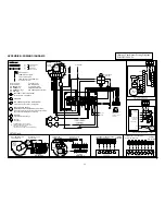
Thermostat wiring connections and air conditioning
contactor low voltage connections are shown in the
wiring diagrams in Appendix B. Some micro-
electronic thermostats require additional controls
and wiring. Refer to the thermostat manufacturer's
instructions.
The thermostat should be located approximately 5
feet above the floor, on an inside wall where there is
good natural air circulation, and where the
thermostat will be exposed to average room
temperatures. Avoid locations where the thermostat
will be exposed to cold drafts, heat from nearby
lamps and appliances, exposure to sunlight, heat
from inside wall stacks, etc.
The thermostat heat anticipator should be adjusted
to the amperage draw of the heating control circuit
as measured at the "R" and "W" terminals of the
thermostat. To reduce the risk of damaging the heat
anticipator, do not measure this current with the
thermostat connected to the circuit. Measure the
amperage by connecting an ammeter between the
two wires that will connect to the thermostat "R" and
"W" terminals.
11. HUMIDIFIER
A humidifier is an optional accessory available
through most heating supplies outlets. Installation
should be carried out in accordance with the
humidifier manufacturer's installation instructions.
Water or water droplets from the humidifier should
not be allowed to come into contact with the furnace
heat exchanger. Do not use direct drive motor
connections as a source of power for 120 VAC
humidifiers and humidifier transformers.
12. PIPING INSTALLATION
The entire fuel system should be installed in
accordance with the requirement of CAN/CSA B-
139, and local regulations. Use only an approved
fuel oil tanks piping, fittings and oil filter.
In the United States the installation must be in
accordance with NFPA No. 31 and local codes and
authorities.
Install the oil filter as close to the burner as possible.
For further details of the oil supply tank and piping
requirements, please refer to the instructions and
illustrations in the oil burner and oil pump
instructions shipped with the furnace.
5
Summary of Contents for POF1HD091AVFA
Page 30: ...30...
Page 33: ...33...
Page 36: ...NOTES Nordyne Inc 8000 Phoenix Parkway O Fallon Missouri 63368 766B 0909...


