background image

7

INSTALLATION INSTRUCTIONS
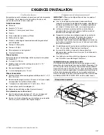
Prepare Location

NOTE: It is recommended that the vent system be installed 
before hood is installed.

Before making cutouts, make sure there is proper clearance 
within the ceiling or wall for exhaust vent.

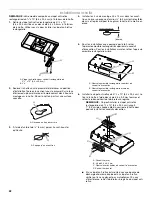
1. Disconnect power.

2. Depending on your model, determine which venting method 

to use: roof or wall. 

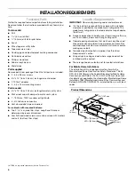
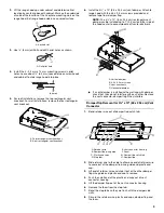
3. Select a flat surface for assembling the range hood. Place 

covering over that surface.

4. Lift the range hood and set it upside down onto covered 

surface.

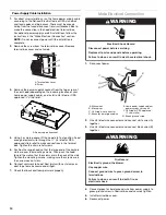
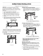
5. If cabinet has recessed bottom, add wood filler strips on each 

side. Install screws to attach filler strips in locations shown.

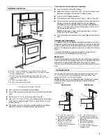
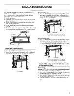
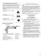
Determine Wiring Hole Location

Cut only one 1

¹⁄₄

" (3.2 cm) diameter wiring access hole. 

1. Determine and clearly mark a vertical centerline on the wall 

and cabinet in the area the vent opening will be made.

To wire through top: 

1. Mark a line distance “A” from the right of the centerline on the 

underside of the cabinet. Mark the point on this line that is 

⁷⁄₈

" (2.2 cm) from back wall. Drill a 1¼" (3.2 cm) diameter hole 

through the cabinet at this point.

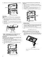
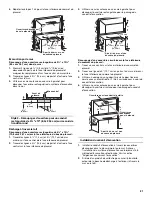
To wire through wall:

1. Mark a line distance “A” from the right of the centerline on the 

underside of the wall. Mark the point on this line that 
is 

⁷⁄₈

" (2.2 cm) from the underside of the cabinet. Drill a 

1

¹⁄₄

" (3.2 cm) diameter hole through the rear wall at this point. 

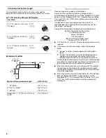
Style 1 - Cut Openings for 3¼" x 10" (8.3 cm x 25.4 cm) 
Rectangular Vent System

Roof Venting

To make a 4

¹⁄₄

" x 10½" (10.8 cm x 26.7 cm) rectangular cutout 

on the underside of cabinet top and bottom:

1. Mark lines 

¹⁄₂

" (1.3 cm) and 4

³⁄₄

" (12.1 cm) from the back wall 

on the centerline of the underside of cabinet.

2. Mark lines 5¼" (13.3 cm) to the right and left of the centerline 

on the underside of cabinet.

3. Use saber or keyhole saw to cut a rectangular opening for 

vent.

A. Centerline

Cabinet
bottom

Wall

3" (7.6 cm)

Wood filler strips

(recessed cabinet

bottoms only)

3" (7.6 cm)

A

A. 8

³⁄₈

" (21.3 cm) for 30" (76.2 cm) models

11

³⁄₈

" (28.9 cm) for 36" (91.4 cm) models

A. 8

³⁄₈

" (21.3 cm) for 30" (76.2 cm) models

11

³⁄₈

" (28.9 cm) for 36" (91.4 cm) models

Centerline

⁷⁄₈

" (2.2 cm)

from wall,
not cabinet
frame

A

A

Centerline

⁷⁄₈

" (2.2 cm)

Summary of Contents for UXT2030AYB

Page 1: ...lpool ca HOTTE D ASPIRATION DE 30 76 2 CM ET 36 91 4 CM Instructionsd installationetGuided utilisationetd entretien Au Canada pour assistance installation ou service composer le 1 800 807 6777 ou visiter notre site Web à www whirlpool ca Table of Contents Table des matières 2 IMPORTANT READ AND SAVE THESE INSTRUCTIONS FOR RESIDENTIAL USE ONLY IMPORTANT LIRE ET CONSERVER CES INSTRUCTIONS POUR UTILI...

Page 2: ...r l installation 24 UTILISATION DE LA HOTTE 24 Commandes de la hotte de cuisinière 25 ENTRETIEN DE LA HOTTE 25 Nettoyage 25 SCHÉMA DE CÂBLAGE 26 ASSISTANCE OU SERVICE 27 Au Canada 27 Accessoires 27 GARANTIE 27 RANGE HOOD SAFETY You can be killed or seriously injured if you don t immediately You can be killed or seriously injured if you don t follow All safety messages will tell you what the potent...

Page 3: ...zardous or explosive materials and vapors CAUTION To reduce risk of fire and to properly exhaust air be sure to duct air outside do not vent exhaust air into spaces within walls or ceilings attics or into crawl spaces or garages WARNING TO REDUCE THE RISK OF FIRE USE ONLY METAL DUCTWORK WARNING TO REDUCE THE RISK OF A RANGE TOP GREASE FIRE Never leave surface units unattended at high settings Boil...

Page 4: ...is the installer s responsibility to comply with installation clearances specified on the model serial rating plate The model serial rating plate is located inside the range hood on the left wall Range hood location should be away from strong draft areas such as windows doors and strong heating vents Cabinet opening dimensions that are shown must be used Given dimensions provide minimum clearance ...

Page 5: ...ures as part of the vent system The damper should be on the cold air side of the thermal break The break should be as close as possible to where the vent system enters the heated portion of the house Makeup Air Local building codes may require the use of makeup air systems when using ventilation systems greater than specified CFM of air movement The specified CFM varies from locale to locale Consu...

Page 6: ...Connect a section of solid copper wire to the pigtail leads 2 Connect the aluminum wiring to the added section of copper wire using special connectors and or tools designed and UL listed for joining copper to aluminum Follow the electrical connector manufacturer s recommended procedure Aluminum copper connection must conform with local codes and industry accepted wiring practices Wire sizes and co...

Page 7: ...ark the point on this line that is 2 2 cm from back wall Drill a 1 3 2 cm diameter hole through the cabinet at this point To wire through wall 1 Mark a line distance A from the right of the centerline on the underside of the wall Mark the point on this line that is 2 2 cm from the underside of the cabinet Drill a 1 3 2 cm diameter hole through the rear wall at this point Style 1 Cut Openings for 3...

Page 8: ...of the top of cabinet 2 Mark a line 5 12 7 cm from the back wall on the underside of the top of cabinet 3 Use a compass or a circle template to draw a circle with a diameter that is 0 64 cm larger than the vent 4 Use saber or keyhole saw to cut the circular vent opening Install Vent System 1 Install vent through the vent opening in upper cabinet or wall Complete venting system according to the sel...

Page 9: ...per check that they do not interfere with each other Remove the vent connector damper flap if they interfere Damper Flap Removal for 3 x 10 8 3 x 25 4 cm Vent Connector 1 Bend retainer wire out of damper flap catch tab 2 Slide retainer wire to the side to allow one end of retainer wire to come out of the damper flap wire guide and plastic end cap 3 Lift end of retainer wire and slide it out of the...

Page 10: ...g screws Then push the hood toward the wall so that the screws are in the neck of the slots Tighten the mounting screws making sure the screws are in the narrow neck of slots 6 Connect ventwork to hood Seal joints with vent clamps or duct tape to make secure and airtight 7 Check that back draft dampers work properly MakeElectricalConnection 1 Disconnect power 2 Use UL listed wire connectors and co...

Page 11: ...fan switch to the middle for Off RANGE HOOD CARE Cleaning IMPORTANT Clean the hood and grease filters frequently according to the following instructions Replace grease filter before operating hood Exterior Surfaces IMPORTANT Do not use soap filled scouring pads abrasive cleaners Cooktop Polishing Creme steel wool gritty washcloths or paper towels To avoid damage to the stainless steel do not use c...

Page 12: ...lots 5 Reconnect power If new light does not operate make sure the lamp is inserted correctly before calling service WIRING DIAGRAM A Light bulb socket B Lens cover A B 0 9 10 A 50 10 Watts 22 3 10 Ohms 13 4 10 Ohms C19 SE116B Motor Characteristics Power Supply 120 VAC Frequency 60 Hz Amperage Wattage Rating Motor Resistance White Red White Black Light Switch On Off Motor Switch Low Off High BK W ...

Page 13: ... service anywhere in the United States To locate the Whirlpool designated service company in your area you can also look in your telephone directory Yellow Pages For further assistance If you need further assistance you can write to Whirlpool Corporation with any questions or concerns at Whirlpool Brand Home Appliances Customer eXperience Center 553 Benson Road Benton Harbor MI 49022 2692 Please i...

Page 14: ...ice by an authorized Whirlpool servicer is not available 10 The removal and reinstallation of your major appliance if it is installed in an inaccessible location or is not installed in accordance with published installation instructions 11 Major appliances with original model serial numbers that have been removed altered or cannot be easily determined This warranty is void if the factory applied s...

Page 15: ...as de non respect des instructions Votre sécurité et celle des autres est très importante Nous donnons de nombreux messages de sécurité importants dans ce manuel et sur votre appareil ménager Assurez vous de toujours lire tous les messages de sécurité et de vous y conformer AVERTISSEMENT DANGER Voici le symbole d alerte de sécurité Ce symbole d alerte de sécurité vous signale les dangers potentiel...

Page 16: ...die et évacuer adéquatement les gaz veiller à acheminer l air aspiré par un conduit jusqu à l extérieur ne pas décharger l air aspiré dans un espace vide du bâtiment comme une cavité murale un plafond un grenier un vide sanitaire ou un garage AVERTISSEMENT POUR RÉDUIRE LE RISQUE D INCENDIE UTILISER UNIQUEMENT DES CONDUITS MÉTALLIQUES AVERTISSEMENT POUR MINIMISER LE RISQUE D UN FEU DE GRAISSE SUR L...

Page 17: ...bilité de respecter les distances de séparation exigées spécifiées sur la plaque signalétique de l appareil La plaque signalétique est située à l intérieur de la hotte sur la paroi de gauche Installer la hotte de cuisinière à distance de toute zone exposée à des courants d air comme fenêtres portes et bouches de chauffage à fort débit Respecter les dimensions indiquées pour les ouvertures à découp...

Page 18: ...n de l intérieur de la maison à l extérieur Le clapet anti reflux doit être placé du côté air froid de la résistance thermique L élément d isolation thermique doit être aussi proche que possible de l endroit où le circuit d évacuation s introduit dans la partie chauffée de la maison Air d appoint Le code du bâtiment local peut exiger l emploi d un système d appoint d air lors de l emploi d un vent...

Page 19: ... suivre les instructions suivantes 1 Connecter une section de câble en cuivre massif aux conducteurs en queue de cochon 2 Connecter le câblage en aluminium à la section ajoutée de câblage en cuivre en utilisant des connecteurs et ou des outils spécialement conçus et homologués UL pour fixer le cuivre à l aluminium Appliquer la procédure recommandée par le fabricant des connecteurs La connexion alu...

Page 20: ...placard Sur cette ligne marquer le point situé à 2 2 cm du mur arrière Percer en ce point un trou de 1 3 2 cm de diamètre à travers le placard Passage du câble à travers le mur 1 Tracer une ligne de distance A à partir de la droite de l axe central sur la face inférieure du mur Marquer un point sur cette ligne qui se trouve à 2 2 cm de la face inférieure du placard Percer en ce point un trou de 1 ...

Page 21: ...cuation Découpage d une ouverture circulaire sur la face inférieure du sommet du placard 1 Tracer un axe central sur la face inférieure du sommet du placard 2 Tracer une ligne de 5 12 7 cm en partant du mur arrière sur la face inférieure du sommet du placard 3 Utiliser un compas ou un gabarit circulaire pour tracer un cercle avec un diamètre de 0 64 cm supérieur à celui du conduit d évacuation 4 U...

Page 22: ...ble rectangulaire supérieur du conduit d évacuation Pour les installations murales retirer l opercule amovible rectangulaire arrière 6 Installer le clapet anti reflux de 3 x 10 8 3 x 25 4 cm Le fixer à la hotte à l aide des vis de 3 5 x 9 5 mm fournies et retirer le ruban adhésif de l obturateur à registre REMARQUE On peut installer le clapet anti reflux rectangulaire de 3 x 10 8 3 x 25 4 cm jusqu...

Page 23: ...facultatif suivre les instructions de la section Raccordement électrique REMARQUE Ne pas mettre le système sous tension avant d avoir complètement terminé l installation 2 Ôter la vis du couvercle du boîtier de connexion Retirer le couvercle du boîtier de connexion et le mettre de côté 3 Ôter l opercule pour le passage de l alimentation électrique du sommet ou de l arrière de la hotte de ventilati...

Page 24: ... hotte UTILISATION DE LA HOTTE La hotte de cuisinière est conçue pour extraire fumée vapeurs de cuisson et odeurs de la zone de la table de cuisson Pour obtenir les meilleurs résultats mettre le ventilateur de la hotte en marche avant d entreprendre une cuisson et laisser le ventilateur fonctionner pendant plusieurs minutes après l achèvement d une cuisson pour pouvoir évacuer de la cuisine toute ...

Page 25: ...Détergent liquide ou nettoyant tout usage Rincer à l eau propre et sécher avec un chiffon doux sans charpie Nettoyant à vitre pour éliminer les traces de doigts Filtre à graisse métallique 1 Ôter la vis de la patte de retenue du filtre à graisse 2 Faire pivoter la patte de retenue du filtre à graisse pour libérer le filtre 3 Laver le filtre métallique selon le besoin au lave vaisselle ou avec une ...

Page 26: ...irage Marche Arrêt Contacteur du moteur Faible Arrêt Élevé Vis de mise à la terre Vitesse 1 Vitesse 2 Commun 0 9 10 A 50 10 Watts 22 3 10 Ohms 13 4 10 Ohms Caractéristiques du moteur Alimentation électrique 120 VCA Fréquence 60 Hz Intensité Puissance nominale Résistance du moteur Blanc Rouge Blanc Noir ...

Page 27: ...ion Le service doit être fourni par une compagnie de service désignée par Whirlpool Cette garantie limitée est valide uniquement aux États Unis ou au Canada et s applique exclusivement lorsque l appareil est utilisé dans le pays où il a été acheté À l extérieur du Canada et des 50 États des États Unis cette garantie limitée ne s applique pas Une preuve de la date d achat original est exigée pour o...

Page 28: ...R D UNE JURIDICTION À UNE AUTRE Si vous résidez à l extérieur du Canada et des 50 États des États Unis contactez votre marchand Whirlpool autorisé pour déterminer si une autre garantie s applique Si vous avez besoin de service voir d abord la section Dépannage du Guide d utilisation et d entretien Après avoir vérifié la section Dépannage de l aide supplémentaire peut être trouvée en vérifiant la s...

Reviews: