background image

17

1031012 Rev.A 09/05

SERVICE PART NUMBER LIST

22

Part Number

Description

0000-8F-H03

Hood Safety Switch Kit

0000-8F-Z01

Remote Start Control Module Service Part

0000-8F-L02

Mazda3 Remote Start Wire Harness Service Part

0000-8F-H05

Mazda3 Immobilizer Interface Service Part

0000-8F-L16

Mazda3 DNA Card Software Service Part

0000-8F-F06

Mazda3 Remote Start Transmitter Service Part

0000-8F-Z10

Dipole Antenna

Rearm the security system and test the shock sensor. This system is equipped with a two stage shock sensor which has

a lite-touch (warn away) trigger and a full trigger. The lite-touch trigger senses for non-damaging shock to the vehicle and

beeps the horn, the full trigger senses for potential damaging shock to the vehicle and triggers the security system. The

shock pressure needed for each trigger is tested by slapping a closed window with the open (flat) palm of your hand.

WARNING - DO NOT WEAR ANY JEWELRY (i.e.. ring or watches) ON THE HAND YOU ARE USING FOR THIS TEST,

DO NOT STRIKE THE BODY PANELS OR USE A CLOSED FIST FOR THIS TEST.

Lite-touch testing - Slap window with non-damaging pressure, increasing pressure until response is obtained- Horn

should beep one time and parking lights should flash one time once shock pressure level is obtained.

Full trigger testing - Increase pressure of slap until response is obtained but be careful not to break window - security

system should trigger. Disarm the security system.

PLACE FACTORY TRANSMITTERS IN GLOVEBOX AND ATTACH NEW 4 BUTTON REMOTE START TRANSMITTERS

TO KEYS. ALSO, PLACE USER INSTRUCTION MANUAL AND WALLET CARD IN GLOVEBOX.

20

Shock Sensor Testing

PowerCode®, IT-s®, Real Panic Sound® and Progressive Find® are registered trademarks of Code Systems, Inc.

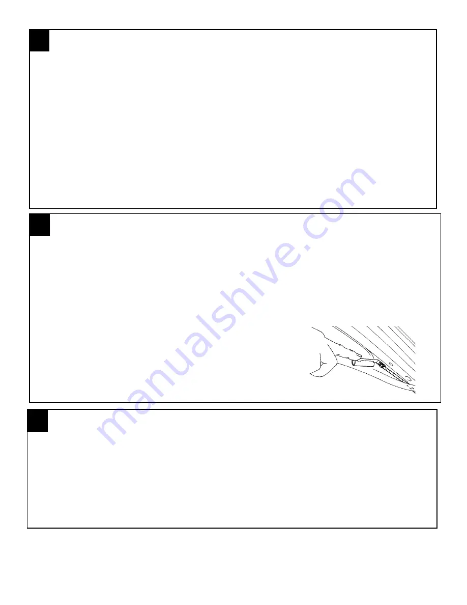
The hood safety will need to be adjusted to shutdown the vehicle when the hood is raised to the full upright position

1. Raise and prop the vehicle’s hood.

2. The hood switch cylinder  should be bend away from the hood to approximately 15 degrees above parallel with the

   ground.  (FIGURE XX)

3. After the adjustment has been made verify that remote start system does not engage when the vehicle’s hood is
    open.

4. If the remote start system engages  with the hood in the full upright position, the switch will need to be bent closer to
    the hood.

21

NOTE: IT IS VERY IMPORTANT TO VERIFY THAT THE HOOD
SAFETY SWITCH PREVENTS THE REMOTE ENGINE START
SYSTEM FROM ENGAGING WHEN THE VEHICLE’S HOOD IS

IN THE FULL UPRIGHT POSITION

FIGURE XX

HOOD SAFETY SWITCH ADJUSTMENT

Summary of Contents for 0000-8F-L10

Page 1: ...ing any service on the vehicle Ce v hicule est dot d un d marreur distance Pour r duire les risques de blessures graves ou mortelles mettre le d marreur distance en mode service et d brancher la batte...

Page 2: ...roud and remove the shroud FIGURE D and E g Remove the lower center console kick panels from both driver and passenger sides by using a fiber stick to pull the plastic center button of the plastic fas...

Page 3: ...the weather seal along the A pillar 2 FIGURE J FIGURE K HOOD SAFETY SWITCH MOUNTING 1 Using 2 supplied 1 4 self drilling screws and 2 supplied lock washers secure the hood safety switch to the drivers...

Page 4: ...wire to harness as shown FIGURE T d Pull fish wire and wiring through hood release cable opening FIGURE L page 3 e Tape the hood safety switch wires against the fish wire and electrical tape in place...

Page 5: ...DOME LIGHT PK LIGHTS DOOR LOCKS 15 TRUNK RELEASE To Immobilizer Interface Module FIGURE Y FIGURE X REMOTE ENGINE START MODULE AND IMMOBILIZER INTERFACE MOUNTING 5 Tie Wraps REMOTE ENGINE START MODULE...

Page 6: ...SAFETY SWITCH MOUNTING WIRE CONNECTIONS 1 Locate the BLACK ORANGE and GRAY RED wire from the remote start system harness 2 Locate the wires listed below If the hood safety switch wire has a ground ri...

Page 7: ...ONNECTION LOCATED AT PIN N OF THE J 04 CONNECTOR TOP OF PJB BLACK REC TRUNK AJAR INPUT CONNECTION LOCATED AT PIN X 5 DR PIN Z 4 DR J 06 CONNECTOR BOTTOM OF PJB BLACK WHITE DOOR UNLOCK OUTPUT LOCATED A...

Page 8: ...tart harness 8 way male connector into the factory ignition harness and replace the GREY secondary latch FIGURE EE MULTIFUNCTION SWITCH CONNECTOR 1 Locate the 12 way WHITE multifunction switch connect...

Page 9: ...FIGURE II and to the ribbon cable 3 Remove the backing from one side of the supplied 2 way tape and apply tape around the transceiver antenna ring black plastic ring around key switch FIGURE JJ keepin...

Page 10: ...e with pliers 10 WIRE HARNESS CONNECTIONS PASSENGER UNDERDASH 1 Route the passenger kick panel harness with six 6 loose wires across the driver s side lower dash using 1 supplied tie wrap secure the h...

Page 11: ...CLE WIRE BLUE DOMELIGHTINPUT OUTPUT BLACK BLUE Pin U FIGURE QQ REMOTE START HARNESS VEHICLE WIRE BLACK HORNOUTPUT BLACK Pin N FIGURE OO RE MOUNT PJB 1 After all connections have been made re mount the...

Page 12: ...the dashboard panel and re mount the rubber weather seal EMERGENCY OVERRIDE PROGRAMMING BUTTON MOUNTING 1 Locate the previously removed driver s side kick panel cover 2 Drill a 9 32 hole at the top o...

Page 13: ...place d Re install 1 phillips screw on the lower left side of the driver s side dashboard panel FIGURE WW and re se cure the hood release handle 14 FIGUREUU FIGURE VV FIGURETT FIGUREWW SYSTEM POWER U...

Page 14: ...seconds The system should flash the parking lights and chirp the horn one time pause for four seconds then start the engine e After the engine is started Press the brake pedal to shutdown the engine T...

Page 15: ...ystem by pressing the unlock button on the transmitter and try starting the vehicle again the vehicle should crank and start at this time shut the vehicle off Remote Engine Start Functions 1 REMOTE EN...

Page 16: ...amming button The horn will beep 4 times indicating the system has entered the option bank c Press the PANIC button to enter the option number The horn will beep the number of times equal to the optio...

Page 17: ...response is obtained Horn should beep one time and parking lights should flash one time once shock pressure level is obtained Full trigger testing Increase pressure of slap until response is obtained...

Page 18: ...EXT SENSOR INPUT MEMORY 2 OUTPUT AUX 4 TRUNK AJAR INPUT TRUNK REL DR S DR UNLK SW INPUT MEMORY 1 OUTPUT AUX 3 REAR DEFROST OUTPUT AUX 2 NOT USED NOT USED NOT USED NOT USED CIRCUIT DESCRIPTION DOOR LO...

Page 19: ...Rev A 09 05 CIRCUIT LAYOUT PAGE 2 of 2 A A CONTINUED ON NEXT DRAWING 1 SPLICE 2 NOTE SPLICES MAY NOT BE LOCATED WHERE SHOWN 22BK GN C103 15 C103 7 22BK C99 30B 22BK WT C100 39B 22BL C99 29 22BK BL 22B...

Reviews: