8
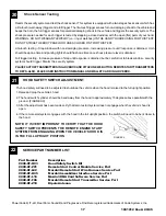
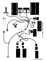
1031012 Rev.A 09/05
WIRE HARNESS CONNECTIONS- STEERING COLUMN
8
IGNITION SWITCH CONNECTOR
1. Spot tape the immobilizer interface ribbon cable wiring to the ignition
harness making sure to leave enough slack to route over to the igni-
tion switch on the right side of the steering column.
2. Route the remote start ignition harness with 8-way male and fe-
male ignition connectors and 12-way male and female multifunction
switch connector, transponder interface wiring and ribbon cable
across and up the left of the steering column harness, do not secure
harness at this time.
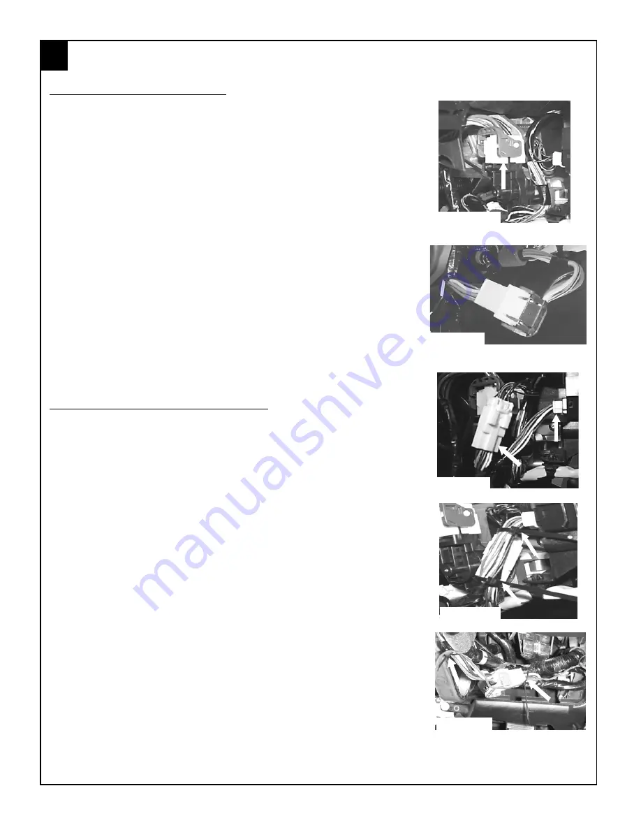
3. Locate the 8-way WHITE and GREY ignition connector, on the left
side of the steering column.
4. Release the GREY secondary latch and remove the 8-way WHITE
ignition connector by pulling upwards.
5. Plug the remote start harness 8-way WHITE female connector into
the factory ignition switch, replace the GREY secondary latch and
secure harness in place. (FIGURE DD)
6. Connect the remote start harness 8-way male connector into the
factory ignition harness, and replace the GREY secondary latch.
(FIGURE EE)
MULTIFUNCTION SWITCH CONNECTOR
1. Locate the 12-way WHITE multifunction switch connector on the left
side of the steering column (plugged into the turn signal assembly).
2. Remove the 12-way connector from the multifunction switch.
3. Plug the 12-way female remote start harness connector into the
multifunction switch. (FIGURE FF)
4. Plug the previously removed vehicle 12-way female connector into
the remote start harness 12-way male connector. (FIGURE FF)
5. Using (2) supplied tie wraps, secure the 12 way multifunction switch
harness to the factory wiring on the left side of the steering column.
(FIGURE GG)
6. Using (2) supplied tie wraps secure the remote start wiring to the
vehicle’s factory ignition wiring. (FIGURE HH)
NOTE: IT IS EXTREMELY IMPORTANT THAT THE WIR-
ING IS SECURED IN A MANNER THAT WILL ALLOW THE
TILT/TELESCOPING STEERING WHEEL TO MOVE
FREELY AND STILL ALLOW FOR REASSEMBLY OF THE
STEERING COLUMN SHROUD. CHECK FUNCTIONAL-
ITY OF THE TILT TELESCOPING STEERING WHEEL
PRIOR TO REASSEMBLY.
FIGURE DD
FIGURE EE
FIGURE HH
FIGURE GG
FIGURE FF


